×
ToyotaParts- Hello
- Login or Register
- Quick Links
- Live Chat
- Track Order
- Parts Availability
- RMA
- Help Center
- Contact Us
- Shop for
- Toyota Parts
- Scion Parts
My Garage
My Account
Cart
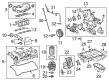
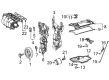
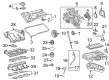
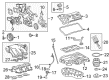
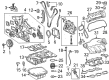
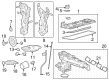
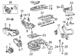
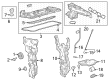
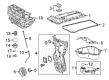
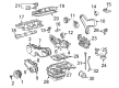
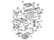
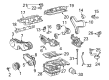
OEM Toyota Highlander Intake Manifold
Engine Intake Manifold- Select Vehicle by Model
- Select Vehicle by VIN
Select Vehicle by Model
orMake
Model
Year
Select Vehicle by VIN
For the most accurate results, select vehicle by your VIN (Vehicle Identification Number).
15 Intake Manifolds found

Toyota Highlander Intake Manifold, Lower Part Number: 17111-0P060
$309.65 MSRP: $442.10You Save: $132.45 (30%)Ships in 1-3 Business Days
Toyota Highlander Intake Manifold Part Number: 17120-F0020
$383.73 MSRP: $562.36You Save: $178.63 (32%)Ships in 1-2 Business Days
Toyota Highlander Manifold, Intake, Lower Part Number: 17111-31141
$404.50 MSRP: $592.80You Save: $188.30 (32%)Ships in 1-3 Business Days
Toyota Highlander Manifold, Intake, Lower Part Number: 17111-0P030
$416.87 MSRP: $610.93You Save: $194.06 (32%)Ships in 1-3 Business Days
Toyota Highlander Manifold, Intake, Lower Part Number: 17111-0P040
$429.70 MSRP: $629.73You Save: $200.03 (32%)Ships in 1-3 Business DaysToyota Highlander Manifold, Intake Part Number: 17120-31070
$451.04 MSRP: $661.00You Save: $209.96 (32%)Ships in 1-3 Business Days
Toyota Highlander Manifold, Intake Part Number: 17120-25080
$485.77 MSRP: $711.90You Save: $226.13 (32%)Ships in 1-3 Business Days
Toyota Highlander Manifold, Intake Part Number: 17101-20070
$328.17 MSRP: $468.55You Save: $140.38 (30%)Ships in 1-3 Business Days
Toyota Highlander Intake Manifold Part Number: 17120-F0100
$347.98 MSRP: $509.97You Save: $161.99 (32%)Ships in 1-2 Business Days

Toyota Highlander Intake Manifold Part Number: 17120-28041
$452.17 MSRP: $662.67You Save: $210.50 (32%)Ships in 1-3 Business Days
Toyota Highlander Intake Manifold, Lower Part Number: 17111-31220
$459.11 MSRP: $672.82You Save: $213.71 (32%)Ships in 1-3 Business Days
Toyota Highlander Manifold, Intake Part Number: 17120-36060
$777.12 MSRP: $1138.88You Save: $361.76 (32%)Ships in 1-3 Business Days
Toyota Highlander Intake Manifold Part Number: 17120-36030
$840.91 MSRP: $1232.36You Save: $391.45 (32%)Ships in 1-3 Business Days

Toyota Highlander Manifold, Intake, Lower Part Number: 17101-20031
Toyota Highlander Intake Manifold Part Number: 17120-28131
Toyota Highlander Intake Manifold
Choose genuine Intake Manifold that pass strict quality control tests. You can trust the top quality and lasting durability. Shopping for OEM Intake Manifold for your Toyota Highlander? Our website is your one-stop destination. We stock an extensive selection of genuine Toyota Highlander parts. The price is affordable so you can save more. It only takes minutes to browse and find the exact fit. Easily add to cart and check out fast. Our hassle-free return policy will keep you stress-free. We process orders quickly for swift delivery. Your parts will arrive faster, so you can get back on the road sooner.
Toyota Highlander Intake Manifold Parts and Q&A
- Q: How to install the intake manifold on Toyota Highlander?A:The installation process for the intake manifold of 2GR-FE engines requires placing two new gaskets on each cylinder head while positioning them properly with port holes aligned. The intake manifold needs to be placed on the cylinder heads before tightening 6 bolts and 4 nuts to 21 Nm (214 kgf-cm, 15 ft-lbf). The installation of the No. 2 engine mounting stay rh requires torqueing bolt [A] to 21 Nm (214 kgf-cm, 15 ft-lbf) then tightening 2 nuts [B] to 23 Nm (234 kgf-cm, 17 ft-lbf) followed by torquing bolt [C] to 38 Nm (387 kgf-cm, 28 ft-lbf) and bolt [D] and three bolts [D] with 8.3 Nm (84 kgf-cm, 73 in-lbf). The fuel delivery pipe sub-assembly receives installation through the placement of six new insulators onto the intake manifold followed by fuel delivery pipe positioning with six Fuel Injectors which requires temporary bolting using five bolts until every injector operates smoothly before reaching 21 Nm (214 kgf-cm, 15 ft-lbf) torque. Use the tube connector to connect the fuel main tube while checking it for damage and dirt then clamp it using No. 2 fuel pipe clamp. Install the intake air surge tank assembly by using 3 new gaskets while maintaining their position and fasten the No. 1 surge tank stay with 2 bolts. Install the throttle body bracket using two bolts at first and afterwards carry out the surge tank installation using four bolts and two nuts while torquing the bolts to 18 Nm (183 kgf-cm, 13 ft-lbf) and the nuts to 16 Nm (163 kgf-cm, 12 ft-lbf). Complete the process by connecting the water by-pass hoses, the connector with the throttle assembly connector and use the four hoses labeled E, F, G and H. Afterward tighten the No. 1 surge tank stay bolts and throttle body bracket bolts to 21 Nm (214 kgf-cm, 15 ft-lbf). Install the engine room main wire harness clamps before mounting the air cleaner cap, outer cowl top panel, windshield Wiper Motor with links, cowl top ventilator louver, and both front wiper arms and blades. The procedure ends with adding engine coolant followed by vital checks for leaks from both engine coolant and fuel systems before putting on the V-bank cover sub-assembly and the No. 1 engine under cover and engine under cover assembly.
- Q: How to remove the intake manifold on Toyota Highlander?A:The first step for removing the intake manifold requires discharging fuel system pressure. Unplug the cable from the negative battery terminal yet remain alert because system initialization procedures could be needed after connection. First remove the Throttle Body assembly before disconnecting both heater water hoses from the inlet and outlet. The process starts with separation of ACIS' vacuum switching valve assembly by detaching its 2 vacuum hoses together with 2 union to connector tube hoses and clamp and connector and finishing with bolt removal. Disconnect the union to connector tube hose in addition to the No. 2 ventilation hose from the intake manifold. The technician should first remove the No. 1 vacuum switching valve assembly with its attached fuel delivery pipe sub-assembly. The intake manifold requires removal by disconnecting four clamps and wire harness and dislodging two bolts while taking off the two wire harness brackets. The procedure starts by detaching the fuel vapor feed hose and vacuum hose with clamp and connector before removing the bolt as well as wire harness bracket. Connect the terminals of the connector to battery voltage between 1 to 3 seconds to shut the tumble control valves but maintain a maximum of 3 seconds to preserve the actuator. Begin by removing the bolt before you sever the two deformable clamps which connect the intake manifold to its bracket along with the detachment of the intake air control valve actuator connector and eventual extraction of the six bolts that fix the intake manifold into position. Any attempt to remove the valves before closing them will likely cause damage to them. Phase one ends with the removal of the intake manifold gasket followed by disconnecting two vacuum hoses from the intake manifold to extract the check valve. The workflow also includes taking the bolt from the wiring harness clamp bracket and extracting the engine mounting damper by removing its three bolts.


Related Toyota Highlander Parts
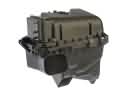 Toyota Highlander Air Filter Box
 Toyota Highlander Fuel Pump
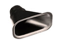 Toyota Highlander Air Duct
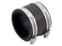 Toyota Highlander Air Intake Coupling
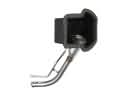 Toyota Highlander Fuel Filler Neck
 Toyota Highlander Fuel Injector O-Rings
 Toyota Highlander Fuel Line Clamps
 Toyota Highlander Fuel Pressure Regulator
 Toyota Highlander Fuel Pump Gasket
 Toyota Highlander Fuel Pump Seal
 Toyota Highlander Fuel Pump Wiring Harness
 Toyota Highlander Intake Manifold Gasket