×
ToyotaParts- Hello
- Login or Register
- Quick Links
- Live Chat
- Track Order
- Parts Availability
- RMA
- Help Center
- Contact Us
- Shop for
- Toyota Parts
- Scion Parts
My Garage
My Account
Cart
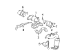
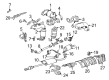
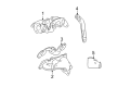
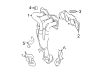
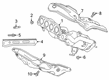
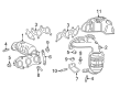
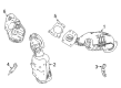
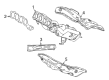
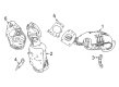
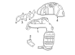
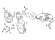
OEM Toyota Highlander Exhaust Manifold
Engine Exhaust Manifold- Select Vehicle by Model
- Select Vehicle by VIN
Select Vehicle by Model
orMake
Model
Year
Select Vehicle by VIN
For the most accurate results, select vehicle by your VIN (Vehicle Identification Number).
31 Exhaust Manifolds found


Toyota Highlander Exhaust Manifold, Driver Side Part Number: 25052-20190
$709.25 MSRP: $883.97You Save: $174.72 (20%)Ships in 1-3 Business Days

Toyota Highlander Exhaust Manifold, Passenger Side Part Number: 25051-20040
$764.75 MSRP: $953.14You Save: $188.39 (20%)Ships in 1-3 Business Days

Toyota Highlander Exhaust Manifold, Passenger Side Part Number: 17140-20120
$558.07 MSRP: $817.86You Save: $259.79 (32%)Ships in 1-3 Business Days


Toyota Highlander Exhaust Manifold, Passenger Side Part Number: 17140-0P210
$713.79 MSRP: $1046.07You Save: $332.28 (32%)Ships in 1-3 Business Days

Toyota Highlander Exhaust Manifold, Driver Side Part Number: 17105-20010
$247.90 MSRP: $353.95You Save: $106.05 (30%)Ships in 1-3 Business Days

Toyota Highlander Exhaust Manifold Part Number: 17141-36050
$334.46 MSRP: $477.53You Save: $143.07 (30%)Ships in 1-3 Business Days
Toyota Highlander Manifold, Exhaust Part Number: 17141-F0010
$652.39 MSRP: $956.08You Save: $303.69 (32%)Ships in 1-2 Business Days
Toyota Highlander Catalytic Converter, Passenger Side Part Number: 17140-0P250
$1006.51 MSRP: $1475.04You Save: $468.53 (32%)
Toyota Highlander Exhaust Manifold, Driver Side Part Number: 17150-0P430
$584.29 MSRP: $856.27You Save: $271.98 (32%)
Toyota Highlander Exhaust Manifold, Passenger Side Part Number: 17140-0P430
$634.45 MSRP: $929.80You Save: $295.35 (32%)
Toyota Highlander Catalytic Converter Part Number: 17141-F0130
$632.64 MSRP: $927.14You Save: $294.50 (32%)Ships in 1-2 Business Days
Toyota Highlander Exhaust Manifold Part Number: 17141-F0150
$656.13 MSRP: $961.57You Save: $305.44 (32%)Ships in 1-3 Business DaysToyota Highlander Exhaust Manifold, Passenger Side Part Number: 17140-0P350
$754.20 MSRP: $1105.28You Save: $351.08 (32%)Ships in 1-3 Business Days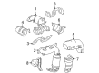
Toyota Highlander Exhaust Manifold, Driver Side Part Number: 17150-0P200
$807.88 MSRP: $1183.96You Save: $376.08 (32%)
Toyota Highlander Manifold, Exhaust, Passenger Side Part Number: 17140-31390
$942.72 MSRP: $1381.56You Save: $438.84 (32%)Ships in 1-3 Business DaysToyota Highlander Exhaust Manifold, Driver Side Part Number: 17150-31270
$1118.42 MSRP: $1639.05You Save: $520.63 (32%)Ships in 1-3 Business DaysToyota Highlander Exhaust Manifold, Passenger Side Part Number: 17140-0P080
$1182.09 MSRP: $1732.37You Save: $550.28 (32%)Ships in 1-3 Business Days
Toyota Highlander Exhaust Manifold, Driver Side Part Number: 17150-31380
$1510.67 MSRP: $2213.90You Save: $703.23 (32%)Ships in 1-3 Business DaysToyota Highlander Exhaust Manifold, Passenger Side Part Number: 17140-31410
$1510.67 MSRP: $2213.90You Save: $703.23 (32%)Ships in 1-3 Business Days
Toyota Highlander Manifold Assembly, Exhaust Part Number: 17140-0P331
$903.56 MSRP: $1324.18You Save: $420.62 (32%)
| Page 1 of 2 |Next >
1-20 of 31 Results
Toyota Highlander Exhaust Manifold
Choose genuine Exhaust Manifold that pass strict quality control tests. You can trust the top quality and lasting durability. Shopping for OEM Exhaust Manifold for your Toyota Highlander? Our website is your one-stop destination. We stock an extensive selection of genuine Toyota Highlander parts. The price is affordable so you can save more. It only takes minutes to browse and find the exact fit. Easily add to cart and check out fast. Our hassle-free return policy will keep you stress-free. We process orders quickly for swift delivery. Your parts will arrive faster, so you can get back on the road sooner.
Toyota Highlander Exhaust Manifold Parts and Q&A
- Q: How to remove the exhaust manifold on Toyota Highlander?A:The process of removing the 2GR-FE engine exhaust manifold begins with removing the right-hand front wheel then continuing with V-bank cover sub-assembly removal. The first step involves separating the engine under cover assembly and then eliminating both No. 1 and No. 2 engine under covers. Start the repair procedure by draining the engine coolant before separating the hose for radiator connection No. 1. The radiator reserve tank assembly can be removed by disconnecting hose [A] and removing 2 bolts [B]. Proceed to eliminate the No. 2 oil level dipstick guide and the air fuel ratio sensor for Bank 2 Sensor 1. Uninstall the No. 2 exhaust manifold heat insulator through the removal of its 3 bolts. Start by separating the propeller with center bearing shaft assembly when operating on 4WD models followed by the tail Exhaust Pipe assembly, center exhaust pipe assembly, front No. 3 exhaust pipe sub-assembly and front exhaust pipe assembly. Restore access to the No. 2 manifold stay after deleting its bolt and nut then disconnect the exhaust manifold sub-assembly LH by extracting all 6 nuts and removing its gasket. Set aside the manifold stay after removing its bolt and nut and disconnect the Bank 1 Sensor 1 air fuel ratio sensor connector and detach its clamp. To finish the repair disconnect all 6 nuts which detach the exhaust manifold sub-assembly RH as well as its gasket.
- Q: How to install the exhaust manifold on Toyota Highlander?A:The Air Fuel Ratio Sensor needs installation first before proceeding with the exhaust manifold setup. You should install the No. 2 exhaust manifold heat insulator using a bolt tightened to 25 Nm (250 kgf-cm, 18 ft-lbf). Use a new gasket to cover the cylinder head before securing the exhaust manifold assembly with 5 nuts according to sequence and torque them to 35 Nm (357 kgf-cm, 26 ft-lbf). Proceed with installing the plate and bolt it to the manifold before tightening until it reaches 25 Nm torque (250 kgf-cm and 18 ft-lbf). Connect the No. 2 manifold stay using a bolt with nut combinations that must be torqued to 43 Nm. Attach the wire harness bracket with a single bolt torqued to 12 Nm. Finally set the manifold stay into place with a bolt and nut which should be torqued to 43 Nm (438 kgf-cm, 32 ft-lbf). Before installing the front Exhaust Pipe assembly verify the compression spring's free length using a vernier caliper because it needs to measure 41.5 mm (1.64 in.)+ immediately replace if the length is less than required. Using a plastic hammer together with a wooden block properly place a new gasket into the exhaust manifold assembly before checking for correct installation without reusing or damaging the component. Insert a second new gasket to the front exhaust pipe before securing it with 2 compression springs and 4 bolts that need torquing up to 48 Nm (489 kgf-cm, 35 ft-lbf) and 56 Nm (571 kgf-cm, 41 ft-lbf) respectively. Finally connect the clamp and connector. Lastly, attach the 3 clips before screwing the front floor cover LH with its 2 screws and 4 bolts. This process requires the under No. 1 engine cover to be installed afterward.


Related Toyota Highlander Parts
 Toyota Highlander Catalytic Converter
 Toyota Highlander Muffler
 Toyota Highlander Canister Purge Valve
 Toyota Highlander Diverter Valve
 Toyota Highlander EGR Tube
 Toyota Highlander EGR Valve Gasket
 Toyota Highlander Exhaust Flange Gasket
 Toyota Highlander Exhaust Hanger
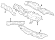
 Toyota Highlander Exhaust Heat Shield
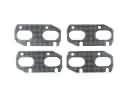 Toyota Highlander Exhaust Manifold Gasket
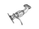 Toyota Highlander Exhaust Pipe
 Toyota Highlander Vapor Pressure Sensor