×
ToyotaParts- Hello
- Login or Register
- Quick Links
- Live Chat
- Track Order
- Parts Availability
- RMA
- Help Center
- Contact Us
- Shop for
- Toyota Parts
- Scion Parts
My Garage
My Account
Cart
OEM 2002 Toyota Highlander Camshaft
Cam- Select Vehicle by Model
- Select Vehicle by VIN
Select Vehicle by Model
orMake
Model
Year
Select Vehicle by VIN
For the most accurate results, select vehicle by your VIN (Vehicle Identification Number).
6 Camshafts found

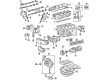
2002 Toyota Highlander Camshaft Sub-Assembly, No
Part Number: 13502-20902$549.67 MSRP: $805.55You Save: $255.88 (32%)Ships in 1-3 Business DaysProduct Specifications- Other Name: CAMSHAFT SUB-ASSY,NO; Camshaft
- Item Weight: 6.30 Pounds
- Item Dimensions: 21.7 x 3.4 x 2.9 inches
- Condition: New
- SKU: 13502-20902
- Warranty: This genuine part is guaranteed by Toyota's factory warranty.

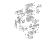
2002 Toyota Highlander Camshaft Sub-Assembly, No
Part Number: 13054-20902$549.67 MSRP: $805.55You Save: $255.88 (32%)Ships in 1-3 Business DaysProduct Specifications- Other Name: CAMSHAFT SUB-ASSY,NO; Camshaft
- Replaces: 13054-20020, 13054-0A030
- Item Weight: 6.90 Pounds
- Item Dimensions: 20.8 x 3.6 x 3.0 inches
- Condition: New
- SKU: 13054-20902
- Warranty: This genuine part is guaranteed by Toyota's factory warranty.

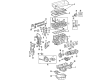
2002 Toyota Highlander Camshaft
Part Number: 13502-28010$349.00 MSRP: $511.46You Save: $162.46 (32%)Ships in 1-3 Business DaysProduct Specifications- Other Name: Camshaft Sub-Assembly
- Replaces: 13502-0H010, 13502-0H020
- Part Name Code: 13512
- Item Weight: 4.20 Pounds
- Item Dimensions: 20.9 x 3.4 x 2.9 inches
- Condition: New
- Fitment Type: Direct Replacement
- SKU: 13502-28010
- Warranty: This genuine part is guaranteed by Toyota's factory warranty.

2002 Toyota Highlander Camshaft
Part Number: 13501-28010$349.00 MSRP: $511.46You Save: $162.46 (32%)Ships in 1-3 Business DaysProduct Specifications- Other Name: Camshaft Sub-Assembly
- Manufacturer Note: (J)
- Replaces: 13501-0H010
- Part Name Code: 13511
- Item Weight: 4.50 Pounds
- Item Dimensions: 21.3 x 3.6 x 3.2 inches
- Condition: New
- Fitment Type: Direct Replacement
- SKU: 13501-28010
- Warranty: This genuine part is guaranteed by Toyota's factory warranty.

2002 Toyota Highlander Camshaft
Part Number: 13501-20040$315.59 MSRP: $450.58You Save: $134.99 (30%)Ships in 1-3 Business DaysProduct Specifications- Other Name: Camshaft Sub-Assembly
- Manufacturer Note: (J)
- Replaces: 13501-0A030
- Part Name Code: 13511
- Item Weight: 4.70 Pounds
- Item Dimensions: 21.3 x 3.4 x 3.0 inches
- Condition: New
- Fitment Type: Direct Replacement
- SKU: 13501-20040
- Warranty: This genuine part is guaranteed by Toyota's factory warranty.

2002 Toyota Highlander Camshaft
Part Number: 13053-20030$324.56 MSRP: $463.40You Save: $138.84 (30%)Ships in 1-3 Business DaysProduct Specifications- Other Name: Camshaft Sub-Assembly
- Manufacturer Note: (J)
- Replaces: 13053-0A030
- Part Name Code: 13053
- Item Weight: 4.80 Pounds
- Item Dimensions: 21.4 x 3.6 x 3.0 inches
- Condition: New
- Fitment Type: Direct Replacement
- SKU: 13053-20030
- Warranty: This genuine part is guaranteed by Toyota's factory warranty.
2002 Toyota Highlander Camshaft
Looking for affordable OEM 2002 Toyota Highlander Camshaft? Explore our comprehensive catalogue of genuine 2002 Toyota Highlander Camshaft. All our parts are covered by the manufacturer's warranty. Plus, our straightforward return policy and speedy delivery service ensure an unparalleled shopping experience. We look forward to your visit!
2002 Toyota Highlander Camshaft Parts Q&A
- Q: How to replace the camshaft (RH) on 2002 Toyota Highlander?A: To replace the camshaft (RH), begin by draining the coolant and removing the V-bank cover, front suspension brace sub-assembly upper center, air cleaner assembly with hose, intake air surge tank, ignition coil assembly, cylinder head cover sub-assembly, front wheel RH, front fender apron seal RH, V (cooler compressor to crankshaft pulley) belt No. 1, vane pump V belt, engine moving control rod, engine mounting stay No. 2 RH, generator bracket No. 2, and crankshaft pulley using Special Service Tool: 09213-54015 (91651-60855), 09330-00021, 09950-50013 (09951-05010, 09952-05010, 09953-05010, 09954-05030). Special Service Tool: 09960-10010 (09962-01000, 09963-01000) and 09249-63010 should be used to remove the bolts from both RH and LH timing pulleys after removing timing belt No. 1 cover, timing belt No. 2 cover, transverse engine mounting bracket, timing belt guide No. 2, timing belt, timing belt idler sub-assembly No. 2, and camshaft timing pulley. Hold the camshaft at level position during extraction to avoid damage then match timing marks between drive and driven gears before fixing the exhaust camshaft sub-gear to main gear with a service bolt torqued to 5.4 Nm while you should loosen and remove bearing cap bolts in a specific order to release the camshaft. Perform the same procedure to remove the No. 2 camshaft while also taking out the oil seal afterward. Install a hexagon wrench head into a vise to begin removal of the lock nut using a 46 mm socket wrench (turn it counterclockwise because it has LH threads). Then remove the camshaft VVT-i from the gear without disturbing its 3 bolts. Attach the camshaft by first positioning the knock pin within the groove before putting oil on both surfaces then tightening the new locking nut to 150 plus or minus 5 Nm. The sub-gear process must be completed first followed by the new No. 2 camshaft installation and the sub-gear install steps with correct alignment and torque requirements. Position the No. 2 camshaft level before applying fresh engine oil on the bearing caps then torquing them to 16 Nm. Next install the timing belt No. 3 cover while inspecting its gasket (replace if damaged) then apply necessary belt seal packing before placing the camshaft timing pulley (torque to 125 Nm for both RH and LH pulleys), timing belt idler sub-assembly No. 2 (torque 43 Nm) followed by timing belt installation. The repair process includes reinstalling the transverse engine mounting bracket with 28 Nm torque then continuing with timing belt No. 2 cover followed by timing belt No. 1 cover and crankshaft pulley installation using Special Service Tool: 09213-54015 (91651-60855), 09330-00021 as well as generator bracket No. 2 with 28 Nm torque alongside engine mounting stay No. 2 RH and engine moving control rod. Finally, inspect and adjust valve clearance using Special Service Tool: 09248-55040 (09248-05410, 09248-05420), install the vane pump V belt, V (cooler compressor to crankshaft pulley) belt No. 1, inspect drive belt deflection and tension, and reinstall the cylinder head cover sub-assembly, ignition coil assembly (torque: 8.0 Nm), intake air surge tank, air cleaner assembly with hose, connect the vacuum hose, reinstall the front suspension brace sub-assembly upper center (torque: 80 Nm), V-bank cover, front wheel RH (torque: 103 Nm), add coolant, and inspect for leaks.
Related 2002 Toyota Highlander Parts
 2002 Toyota Highlander Timing Belt
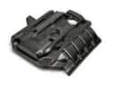 2002 Toyota Highlander Engine Cover
 2002 Toyota Highlander Cam Gear
 2002 Toyota Highlander Crankshaft Thrust Washer Set
 2002 Toyota Highlander Cylinder Head
 2002 Toyota Highlander Dipstick Tube
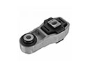 2002 Toyota Highlander Engine Mount Torque Strut
 2002 Toyota Highlander Exhaust Valve
 2002 Toyota Highlander Harmonic Balancer
 2002 Toyota Highlander Oil Pump
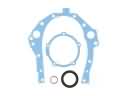 2002 Toyota Highlander Timing Cover Gasket
 2002 Toyota Highlander Valve Stem Seal