×
ToyotaParts- Hello
- Login or Register
- Quick Links
- Live Chat
- Track Order
- Parts Availability
- RMA
- Help Center
- Contact Us
- Shop for
- Toyota Parts
- Scion Parts
My Garage
My Account
Cart
OEM Toyota Prius Camshaft
Cam- Select Vehicle by Model
- Select Vehicle by VIN
Select Vehicle by Model
orMake
Model
Year
Select Vehicle by VIN
For the most accurate results, select vehicle by your VIN (Vehicle Identification Number).
8 Camshafts found

Toyota Prius Camshaft Part Number: 13502-21021
$238.11 MSRP: $339.97You Save: $101.86 (30%)Ships in 1-3 Business Days
Toyota Prius Camshaft Part Number: 13501-21060
$314.54 MSRP: $449.09You Save: $134.55 (30%)Ships in 1-3 Business Days
Toyota Prius Exhaust Camshaft Part Number: 13502-37070
$313.72 MSRP: $447.93You Save: $134.21 (30%)Ships in 1-3 Business Days
Toyota Prius Camshaft Part Number: 13502-37090
$323.78 MSRP: $462.27You Save: $138.49 (30%)Ships in 1-3 Business Days
Toyota Prius Intake Camshaft Part Number: 13501-37080
$331.90 MSRP: $473.88You Save: $141.98 (30%)Ships in 1-3 Business Days
Toyota Prius Camshaft Part Number: 13501-37030
$331.90 MSRP: $473.88You Save: $141.98 (30%)Ships in 1-3 Business Days
Toyota Prius Camshaft Part Number: 13502-37040
$345.41 MSRP: $493.16You Save: $147.75 (30%)Ships in 1-3 Business Days
Toyota Prius Camshaft Part Number: 13501-21040
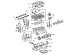
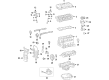
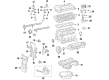
Toyota Prius Camshaft
Choose genuine Camshaft that pass strict quality control tests. You can trust the top quality and lasting durability. Shopping for OEM Camshaft for your Toyota Prius? Our website is your one-stop destination. We stock an extensive selection of genuine Toyota Prius parts. The price is affordable so you can save more. It only takes minutes to browse and find the exact fit. Easily add to cart and check out fast. Our hassle-free return policy will keep you stress-free. We process orders quickly for swift delivery. Your parts will arrive faster, so you can get back on the road sooner.
Toyota Prius Camshaft Parts and Q&A
- Q: How to replace the camshaft (RH or LH) on Toyota Prius?A:The replacement of the camshaft (RH or LH, 1NZ-FXE) starts with removing rear floor board No.2, deck floor box rear, and rear floor board No.3. Start the procedure by disconnecting the battery terminal then removing the engine under cover RH, windshield wiper link assembly, cowl top panel sub-assembly outer front, radiator support opening cover, and air cleaner assembly from the vehicle. You should suspend the brake master cylinder reservoir sub-assembly before removing its reservoir bracket and cylinder head cover sub-assembly. Check the camshaft timing gear marks after performing these steps: set the No. 1 cylinder to TDC/compression by directing the crankshaft damper in a clockwise motion until its timing mark notch reaches "0". Trace marks on the timing chain plates which correspond to camshaft timing gear marks. Use Special Service Tool: 09023-38400 with its 8 mm socket hexagon wrench to remove the service hole screw plug. Subsequently, apply a screwdriver to keep the stopper plate of the chain tensioner elevated while removing the plug. An adjustable wrench should be used to shift the right side hexagonal lobe of camshaft No. 2 until the chain tensioner's plunger is pushed out before removing the screwdriver while maintaining wrench pressure. Thread a 3.0 mm (0.118 inch) diameter bar into the hole of the stopper plate while attaching tape and grip the hexagonal lobe of camshaft No. 2. Special Service Tool: 09023-38400 lets the technician loose the bolt and remove camshaft bearing caps No. 1 and No. 2 in their correct order as long as the camshaft stays at a level position. A gentle upward lift of camshaft No. 2 will allow its removal together with the camshaft timing gear. Set the camshaft timing gear assembly into a vice for holding before covering its oil paths with vinyl tape and puncturing the tape followed by applying air pressure of 150 kPa (1.5 kgf/cm2). Confirm that the camshaft timing gear assembly rotates in advance direction before removing the air pressure in specific order to disconnect the bolt and gear assembly while keeping the remaining four bolts intact. To install the camshaft timing gear assembly position it accurately with respect to the camshaft while gently rotating the left with the straight pin. Tighten the bolt to 64 Nm (653 kgf-cm) with 47 ft. lbs. while maintaining the safety of the camshaft. Before camshaft installation, apply oil to the cam and cylinder head journal. Then mount the camshaft together with its timing gear assembly and align the paint mark of the chain to the timing mark of the assembly. Tighten bearing cap No. 2 bolts to 13 Nm (130 kgf-cm) followed by bearing cap No. 1 bolts to 23 Nm (235 kgf-cm) according to the specified bolt sequence. Use Special Service Tool: 09023-38400 to tighten the bolt on camshaft No. 2 to 64 Nm (653 kgf-cm, 47 ft. lbs.). After this, remove the 3.0 mm (0.118 inch) diameter bar. The crankshaft damper requires clockwise rotation until its timing mark notch appears at "0" while you verify the timing marks. Apply adhesive to the service hole screw plug bolt end, install it using an 8 mm socket hexagon wrench to 15 Nm (153 kgf-cm, 11 ft. lbs.), inspect and adjust valve clearance using Special Service Tool 10514, 09023-38400, then install the cylinder head cover sub-assembly, reservoir bracket (8.5 Nm (87 kgf-cm, 75 inch lbs.)), brake master cylinder reservoir sub-assembly (8.5 Nm (87 kgf-cm, 75 inch lbs.)), air cleaner assembly (7.0 Nm (71 kgf-cm, 62 inch lbs.) for bolt and 3.0 Nm (31 kgf-cm, 27 inch lbs.) for clamp), cowl top panel sub-assembly outer front, windshield wiper link assembly, and check for engine oil leaks. The service concludes with radiator support opening cover installation, engine under cover RH attachment and negative battery terminal reconnection (6.0 Nm (61 kgf-cm, 53 inch lbs.)) before rear floor board No.3 installation and deck floor box rear and rear floor board No.2. The power window control system requires initialization to complete.

Related Toyota Prius Parts
 Toyota Prius Oil Filter
 Toyota Prius Engine Mount
 Toyota Prius Oil Pump
 Toyota Prius Cylinder Head
 Toyota Prius Cylinder Head Gasket
 Toyota Prius Dipstick Tube
 Toyota Prius Intake Valve
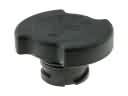 Toyota Prius Oil Filler Cap
 Toyota Prius Piston Ring Set
 Toyota Prius Rod Bearing
 Toyota Prius Spool Valve
 Toyota Prius Variable Timing Sprocket