×
ToyotaParts- Hello
- Login or Register
- Quick Links
- Live Chat
- Track Order
- Parts Availability
- RMA
- Help Center
- Contact Us
- Shop for
- Toyota Parts
- Scion Parts
My Garage
My Account
Cart
OEM Toyota Brake Master Cylinder
- Select Vehicle by Model
- Select Vehicle by VIN
Select Vehicle by Model
orMake
Model
Year
Select Vehicle by VIN
For the most accurate results, select vehicle by your VIN (Vehicle Identification Number).
469 Brake Master Cylinders found


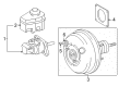
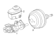
Toyota Brake Booster Assembly, W/Master Cylinder Part Number: 47050-60010
$1358.81 MSRP: $1991.35You Save: $632.54 (32%)Ships in 1-3 Business DaysProduct Specifications- Other Name: Cylinder Assembly, Brake; ABS Pump And Motor Assembly; Brake Master Cylinder; ABS Control Module
- Replaces: 47210-60010


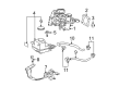
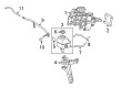
Toyota Brake Booster Part Number: 47050-52020
$784.18 MSRP: $1149.23You Save: $365.05 (32%)Ships in 1-3 Business DaysProduct Specifications- Other Name: Cylinder Assembly, Brake; Brake Master Cylinder; Master Cylinder Assembly; Brake Booster Assembly, W/Master Cylinder


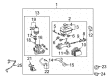
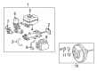
Toyota Brake Booster Part Number: 47050-47110
$1316.36 MSRP: $1929.14You Save: $612.78 (32%)Ships in 1-3 Business DaysProduct Specifications- Other Name: Cylinder Assembly, Brake; Brake Master Cylinder; Master Cylinder Assembly; Brake Booster Assembly, W/Master Cylinder


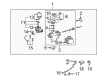
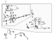
Toyota Brake Booster Assembly, W/Master Cylinder Part Number: 47050-60043
$1369.03 MSRP: $2006.33You Save: $637.30 (32%)Ships in 1-3 Business DaysProduct Specifications- Other Name: Cylinder Assembly, Brake; ABS Pump And Motor Assembly; Brake Master Cylinder; ABS Control Module


Toyota Master Cylinder Part Number: 47028-04030
$253.49 MSRP: $361.93You Save: $108.44 (30%)Ships in 1-3 Business DaysProduct Specifications- Other Name: Cylinder Sub-Assembly, Brake Stroke Simulator; Brake Master Cylinder; Cylinder Sub-Assembly, Brake Master W/Plate
- Manufacturer Note: MEXICO SPEC(W/O (VSC, SIDE & *CUSA))


Toyota Brake Booster Part Number: 47050-47190
$566.34 MSRP: $829.98You Save: $263.64 (32%)Ships in 1-3 Business DaysProduct Specifications- Other Name: Cylinder Assembly, Brake; Brake Master Cylinder; Master Cylinder Assembly; Brake Booster Assembly, W/Master Cylinder


Toyota Brake Booster Assembly, W/Master Cylinder Part Number: 47050-60081
$1369.03 MSRP: $2006.33You Save: $637.30 (32%)Ships in 1-3 Business DaysProduct Specifications- Other Name: Cylinder Assembly, Brake; ABS Pump And Motor Assembly; ABS Control Module
- Replaces: 47050-60080


Toyota Brake Booster Part Number: 47050-35031
$1401.37 MSRP: $2053.73You Save: $652.36 (32%)Ships in 1-3 Business DaysProduct Specifications- Other Name: Cylinder Assembly, Brake; ABS Modulator Valve; ABS Pump And Motor Assembly; ABS Control Module; Actuator Assembly; Brake Booster Assembly, W/Master Cylinder


Toyota Brake Booster Part Number: 47050-35041
$1401.37 MSRP: $2053.73You Save: $652.36 (32%)Ships in 1-3 Business DaysProduct Specifications- Other Name: Cylinder Assembly, Brake; Power Booster; Brake Booster Assembly, W/Master Cylinder
- Replaces: 47050-35040


Toyota Master Cylinder Part Number: 47207-0C010
$368.86 MSRP: $540.57You Save: $171.71 (32%)Ships in 1-2 Business DaysProduct Specifications- Other Name: Cylinder Sub-Assembly, Brake Stroke Simulator; Brake Master Cylinder; Cylinder Sub-Assembly, Brake Master
- Replaces: 47207-34010


Toyota Master Cylinder Part Number: 47050-33110
$631.17 MSRP: $925.00You Save: $293.83 (32%)Ships in 1-3 Business DaysProduct Specifications- Other Name: Cylinder Assembly, Brake; Brake Master Cylinder; Brake Booster; Brake Booster Assembly, W/Master Cylinder


Toyota Cylinder Sub-Assembly, Brake Master Part Number: 47025-60081
$1205.93 MSRP: $1767.30You Save: $561.37 (32%)Ships in 1-2 Business DaysProduct Specifications- Other Name: Cylinder Sub-Assembly, Brake Stroke Simulator; Brake Master Cylinder; Brake Reservoir
- Replaces: 47025-60080


Toyota Master Cylinder Part Number: 47201-04170
$130.06 MSRP: $184.12You Save: $54.06 (30%)Ships in 1-3 Business DaysProduct Specifications- Other Name: Cylinder Sub-Assembly, Brake Stroke Simulator; Brake Master Cylinder; Cylinder Sub-Assembly, Brake Master
- Replaces: 47201-04150


Toyota Actuator Assembly Part Number: 47050-35010
$1369.03 MSRP: $2006.33You Save: $637.30 (32%)Product Specifications- Other Name: Cylinder Assembly, Brake; ABS Modulator Valve; ABS Pump And Motor Assembly; ABS Control Module; Brake Booster Assembly, W/Master Cylinder

Toyota Brake Booster Part Number: 47050-47150
$550.51 MSRP: $806.78You Save: $256.27 (32%)Product Specifications- Other Name: Cylinder Assembly, Brake; Brake Master Cylinder; Master Cylinder Assembly; Brake Booster Assembly, W/Master Cylinder
- Replaces: 47050-47070

Toyota Master Cylinder Part Number: 47050-33112
$631.17 MSRP: $925.00You Save: $293.83 (32%)Ships in 1-3 Business DaysProduct Specifications- Other Name: Cylinder Assembly, Brake; Brake Master Cylinder; Brake Booster; Brake Booster Assembly, W/Master Cylinder


Toyota Actuator Assembly Part Number: 47050-35030
$1369.03 MSRP: $2006.33You Save: $637.30 (32%)Ships in 1-3 Business DaysProduct Specifications- Other Name: Cylinder Assembly, Brake; ABS Modulator Valve; ABS Pump And Motor Assembly; ABS Control Module; Brake Booster Assembly, W/Master Cylinder


Toyota Master Cylinder Assembly Part Number: 47050-47310
$552.46 MSRP: $809.64You Save: $257.18 (32%)Product Specifications- Other Name: Cylinder Assembly, Brake; Brake Master Cylinder; Brake Booster Assembly, W/Master Cylinder
- Manufacturer Note: MARK=47210-47470


Toyota Brake Booster Part Number: 47050-47140
$564.38 MSRP: $827.10You Save: $262.72 (32%)Product Specifications- Other Name: Cylinder Assembly, Brake; Brake Master Cylinder; Master Cylinder Assembly; Brake Booster Assembly, W/Master Cylinder
- Manufacturer Note: MARK=47210-47310


Toyota Brake Booster Part Number: 47050-47180
$568.34 MSRP: $832.91You Save: $264.57 (32%)Product Specifications- Other Name: Cylinder Assembly, Brake; Brake Master Cylinder; Master Cylinder Assembly; Brake Booster Assembly, W/Master Cylinder
- Manufacturer Note: MARK=47210-47350
| Page 1 of 24 |Next >
1-20 of 469 Results
Toyota Brake Master Cylinder
OEM parts deliver unmatched quality you can rely on. They pass extensive quality control inspections. Toyota produces them to the official factory specifications. This process helps prevent defects and imperfections. So you can get exceptional lifespan and a flawless fit. Need new OEM Toyota Brake Master Cylinder? You'll love our wide selection of genuine options. Shop in minutes and skip the hunt. Our prices are unbeatable, you'll save time and money. It's easy to shop and find the right piece. Our committed customer service team gives professional help from start to finish. Every part includes a manufacturer's warranty. We ship quickly, your parts will arrive fast at your door.
Toyota Brake Master Cylinder converts the force of the pedal to a constant hydraulic force, which provides drivers with sharp, predictable stops. Toyota started as a Japanese company by cutting down waste and giving factory workers power to become a global company. Toyota uses the TNGA platform in reducing weight, hardening bodies, and making each model feel livelier. Toyota continues with hybrids, introducing longer electric distances such as the 42-mile RAV4 plug-in that allows skipping gas by commuters. The loyalty of Toyota customers is that its motor vehicles are able to absorb decades of abuse and still be driven to work every morning without a single complaint. This company is obsessed with the concept of continuous improvement; thus, production lines are stopped immediately a fault is detected and time and money are saved. Its hybrid nature also helps in the reduction of emissions in cities without compromising the long-haul range that drivers enjoy on their road trips. Brake Master Cylinder is placed in front and is filled with fluid that pushes through two circuits as soon as the pedal is released. There are also paired pistons and tight seals in the aluminum housing that press that fluid down both lines; therefore, even with one line leaking, the other still seals the pads. Brake Master Cylinder is air bubble, moisture, and corrosion aversive since each pollutant robs the pressure and expands stopping distance. When the fluid leaks around the worn-out cups, the Brake Master Cylinder will become spongy, and the driver will notice this well before the fade becomes hazardous. Periodical flushes ensure that the Brake Master Cylinder is crisp and ready to take the next hard blast.
Toyota Brake Master Cylinder Parts and Q&A
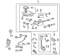
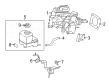
- Q: How to service and repair the brake master cylinder on Toyota 4Runner?A:The first step for brake master cylinder service requires using a 5 mm hexagon wrench to detach the bolt from brake actuator bracket No. 1 and disconnecting the brake fluid level warning switch connector. Use a pin punch and hammer to remove the master cylinder reservoir sub-assembly pin followed by unscrewing the screw and pulling the assembly out, after which remove the master cylinder reservoir filler cap. Remove the three reservoir grommets that exist within the master cylinder reservoir sub-assembly. Using needle nose pliers slide the two brake actuator hose No. 1 clips then pull the hose as well as the clips off. Ctrlexe a union nut wrench to detach brake actuator tube No. 1 from the brake master cylinder. The brake booster attachment procedure for the accumulator pump assembly requires two plug removal with a screwdriver followed by unscrewing the two screws and disconnecting wire harnesses from the master cylinder solenoid before acquiring the assembly with the clip. Another step involves taking out the 2 brake booster pump collars and 2 brake booster pump bushes before removing 2 pins using a 4 mm hexagon wrench. Brace No. 2 connecting the brake booster pump requires removal through two 5 mm hexagon wrench bolts that need to be unscrewed before the pump bush can be taken off. To detach brake actuator bracket No. 3 from its bolt you should then mount the brake booster with accumulator pump assembly in a vise to eliminate the brake booster accumulator assembly and O-ring from the pump while safeguarding it from foreign objects. Sever the brake booster accumulator pipe after you have cut the compression spring. You can remove the master cylinder solenoid by first removing its 6 bolts together with the gasket above them. The process for master cylinder push rod clevis removal starts with loosening the lock nut on the rod operating adapter, proceeding to take out the clevis and lock nut and finally loosening the lock nut on the brake master cylinder side to remove the rod operating adapter and lock nut. Use a screwdriver to push the master cylinder piston while using a pin or equivalent to push the C-ring through the cylinder body hole before removing the piston directly without angling it to protect the cylinder bore.
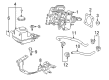
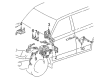
- Q: How to install the brake master cylinder on Toyota Tacoma?A:Before installing the brake master cylinder check and modify the brake booster push rod according to specifications while verifying that brake booster interior remains empty from vacuum atmosphere by stopping the engine then pressing the brake pedal multiple times. Latch Special Service Tool: 09737-00013 onto the master cylinder sub-assembly before dropping the pin until the piston gets a minimal contact. Special Service Tool: 09737-00012 provides an alternative option to perform the task. Set Special Service Tool: 09737-00013 upside down onto the booster with its pin resting on the booster push rod while checking the clearance between the rod and the pin for a 0 mm (0 in.) standard measurement. Use Special Service Tool: 09737-00020 while holding the rod to alter the presentation by turning the tip using a 7 mm socket driver. The procedure involves installation of a new O-ring onto the brake master cylinder sub-assembly and its securement to the brake booster through tightening 2 nuts to 13 Nm (127 kgf-cm, 9 ft-lbf). Use a union nut wrench to apply torque of 20 Nm (199 kgf cm, 14 ft lbf) directly or 18 Nm (187 kgf cm, 13 ft lbf) when using the wrench when installing brake lines onto the master cylinder sub-assembly. The brake fluid level warning switch connector should be attached to the brake master cylinder sub-assembly while connecting the clutch reservoir tube to the manual transmission reservoir. Use a torque wrench to reattach the negative battery terminal with a force of 3.9 Nm but not exceeding 40 kgf-cm or 35 in-lbf. Brake fluid should be added to the reservoir after which the master cylinder bleeding process includes the brake line and brake actuator followed by a fluid level inspection of the reservoir. The last step involves checking for brake fluid leaks before inspecting brake pedal height along with free play and reserve distance.


Related Toyota Parts
 Toyota Brake Caliper
 Toyota Speed Sensor
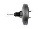 Toyota Brake Booster
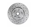 Toyota Brake Rotor
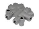 Toyota Brake Proportioning Valve
 Toyota Spindle Nut
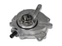 Toyota Vacuum Pump
 Toyota Brake Line
 Toyota Brake Caliper Bracket
 Toyota Hydraulic Hose
 Toyota Parking Brake Shoes
 Toyota Wheel Cylinder Repair Kit
Browse Toyota Brake Master Cylinder by Models
Tacoma 4Runner Camry Tundra Corolla RAV4 Highlander Prius Sienna Land Cruiser Pickup FJ Cruiser 86 Sequoia T100 Avalon Celica Supra Yaris Matrix MR2 Solara Venza GR86 Echo C-HR Cressida Grand Highlander Paseo Previa Prius C Prius Prime bZ4X Corolla Cross Corolla iM GR Corolla Mirai MR2 Spyder Prius V Starlet Tercel Van Yaris iA Prius Plug-In GR Supra Prius AWD-e RAV4 Prime