×
ToyotaParts- Hello
- Login or Register
- Quick Links
- Live Chat
- Track Order
- Parts Availability
- RMA
- Help Center
- Contact Us
- Shop for
- Toyota Parts
- Scion Parts
My Garage
My Account
Cart
OEM Toyota Prius Brake Master Cylinder
- Select Vehicle by Model
- Select Vehicle by VIN
Select Vehicle by Model
orMake
Model
Year
Select Vehicle by VIN
For the most accurate results, select vehicle by your VIN (Vehicle Identification Number).
17 Brake Master Cylinders found


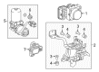
Toyota Prius Brake Booster Part Number: 47050-47190
$566.34 MSRP: $829.98You Save: $263.64 (32%)Ships in 1-3 Business Days
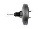
Toyota Prius Brake Booster Part Number: 47050-47150
$550.51 MSRP: $806.78You Save: $256.27 (32%)Toyota Prius Master Cylinder Assembly Part Number: 47050-47320
$552.46 MSRP: $809.64You Save: $257.18 (32%)Ships in 1-3 Business Days
Toyota Prius Brake Booster Part Number: 47050-47J30
$1288.55 MSRP: $1888.39You Save: $599.84 (32%)Ships in 1-3 Business DaysToyota Prius Brake Booster Part Number: 47050-47E90
$1297.52 MSRP: $1901.53You Save: $604.01 (32%)Ships in 1-3 Business DaysToyota Prius Brake Booster Part Number: 47050-47551
$1315.23 MSRP: $1927.48You Save: $612.25 (32%)Ships in 1-3 Business Days
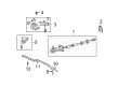
Toyota Prius Master Cylinder Part Number: 47201-47040
$167.78 MSRP: $237.51You Save: $69.73 (30%)Ships in 1-3 Business Days
Toyota Prius Master Cylinder Part Number: 47200-47020
$179.40 MSRP: $256.14You Save: $76.74 (30%)Ships in 1-3 Business Days
Toyota Prius Cylinder Part Number: 47207-47010
$117.96 MSRP: $166.98You Save: $49.02 (30%)Ships in 1-3 Business Days
Toyota Prius Cylinder Assembly, Brake Part Number: 47050-47M02
$1384.92 MSRP: $2029.61You Save: $644.69 (32%)Ships in 1-2 Business Days
Toyota Prius Brake Booster Part Number: 47050-47J40
$1406.02 MSRP: $2060.54You Save: $654.52 (32%)Ships in 1-3 Business DaysToyota Prius Brake Booster Part Number: 47050-47C90
$1406.02 MSRP: $2060.54You Save: $654.52 (32%)Ships in 1-3 Business Days

Toyota Prius Master Cylinder Assembly Part Number: 47050-47310
$552.46 MSRP: $809.64You Save: $257.18 (32%)

Toyota Prius Brake Booster Part Number: 47050-47140
$564.38 MSRP: $827.10You Save: $262.72 (32%)


Toyota Prius Brake Booster Part Number: 47050-47180
$568.34 MSRP: $832.91You Save: $264.57 (32%)Toyota Prius Brake Booster Part Number: 47050-47581
$1387.14 MSRP: $2032.87You Save: $645.73 (32%)
Toyota Prius Master Cylinder Part Number: 47025-47030
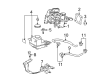
Toyota Prius Brake Master Cylinder
Choose genuine Brake Master Cylinder that pass strict quality control tests. You can trust the top quality and lasting durability. Shopping for OEM Brake Master Cylinder for your Toyota Prius? Our website is your one-stop destination. We stock an extensive selection of genuine Toyota Prius parts. The price is affordable so you can save more. It only takes minutes to browse and find the exact fit. Easily add to cart and check out fast. Our hassle-free return policy will keep you stress-free. We process orders quickly for swift delivery. Your parts will arrive faster, so you can get back on the road sooner.
The Toyota Prius Brake Master Cylinder is one of the most essential requirements of a car's braking system to which people attribute durability and efficiency in different models of Prius. This conventional component transmits the pressure of the driver's foot through hydraulic as a way of enabling the brakes work hard in order to halt the movement of the vehicle. Cross Section of Toyota Prius Brake Master Cylinder: The Toyota Prius Brake Master Cylinder is usually made up of a dual circuit with two pistons; this makes is safer because it has the ability to work on one circuit if the other is faulty. Ever since 1967, this design has been incorporated in vehicles; this aspect shows how Toyota aims at offering dependable braking system. The Brake Master Cylinder may be of the integral type or it may have a separate fluid reservoir and the latest models tend to integrate the later type only. Maintenance is important and any sometime leakage or internal failure can prove to be detrimental to the braking system. The Toyota Prius, which originally came to the market in 1997, has gone through generations in which each generation retained compatibility with the other while bringing changes in aspects of efficiency and safety. One other additional feature that sets the Prius in the market is the ability of the users to choose shift modes and sophisticated safety options. The Toyota Prius Brake Master Cylinder is not only an important component of the car's braking system, but also significantly impacts the car's feel and performance; in turn, it becomes one of the most easily recognizable parts that personify the philosophy of "moving forward" suggested by Toyota.
Toyota Prius Brake Master Cylinder Parts and Q&A
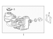
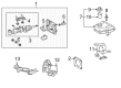
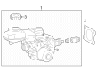
- Q: How to remove the Brake Master Cylinder on Toyota Prius?A:The first step for Brake Master Cylinder removal requires you to take out the windshield Wiper Motor along with its link assembly by dismantling the necessary components. Operation of the pump motor needs to be disabled through brake control off procedures starting with turning off the power switch and removing both No. 1 and No. 2 motor relays to stop air from entering the brake actuator hose. You should start by extracting the bolts to remove both clamps before taking out the outer front cowl top panel sub-assembly. Use proper approaches to remove the inverter with converter from the vehicle system. Brake fluid drainage must occur immediately because contact with paint will cause damage to surfaces. Remove the No. 1 instrument panel register assembly and the lower instrument panel finish panel sub-assembly next in the process. The procedure to remove the brake master cylinder sub-assembly begins with releasing the brake return spring along with its clip and push rod pin and then disconnecting the push rod clevis from the brake pedal before removing clips and reservoir tube hoses. The removal of the actuator bracket bolt requires Special Service Tool: 09023-00101 for the disconnection of front brake tubes No. 1 through 2. To detach the brake tube and 2-way from the brake master cylinder you must first remove its nuts and gasket and master cylinder from the bracket using Special Service Tool: 09023-00101. The technician should finish the job by taking out the push rod clevis after unfastening its lock nut and removing the screw, 1 brake master cylinder union, and grommets.
- Q: How to install the brake master cylinder on Toyota Prius?A:Install the brake master cylinder by attaching the push rod clevis to the brake master cylinder followed by locking the nut while torquing it after brake pedal height adjustment. Use lithium soap base glycol grease to treat 2 new grommets before installing the No. 1 master cylinder union with the 2 grommets to the master cylinder by screw means and torque them up to 1.8 Nm (18 kgf-cm, 16 in-lbf). Special Service Tool: 09023-00101 enables the installation of brake tube together with 2-way to the brake master cylinder which requires torque of 15 Nm (155 kgf-cm, 11 ft-lbf). Attach the brake master cylinder to the bracket and tighten the 2 nuts to 13 Nm (127 kgf-cm, 9 ft-lbf) while installing the gasket between them. The connection between the No. 2 front brake tube and brake master cylinder and clamp requires Special Service Tool: 09023-00101 for torquing up to 15 Nm (155 kgf-cm, 11 ft-lbf). The same tool is needed to connect the No. 1 front brake tube and achieve the same torque setting. Insert the bolt to the actuator bracket while applying torque to 5.0 Nm (51 kgf-cm, 44 in-lbf). Ultimately add and secure the reservoir tube hoses with four clips. The brake master cylinder push rod pin should link the push rod clevis to the brake pedal before installing the clip and brake pedal return spring. The first step is to install the inverter with converter before adding the outer front cowl top panel using 7 bolts that require torquing to 6.4 Nm (65 kgf-cm, 57 in-lbf). Afterward, install 3 clamps to the panel. Use 2 bolts to install the engine room No. 2 R/B while torquing them to 8.4 Nm (86 kgf-cm, 74 in-lbf). Following this fit the windshield Wiper Motor and link assembly together while you should perform fluid installation into the brake reservoir followed by extracting master cylinder and stroke simulator air. The technician must perform brake fluid leak inspections while checking the reservoir fluid level along with brake pedal height adjustment and free play and reserve distance checks. The last steps involve installing the lower instrument panel finish panel together with the No. 1 instrument panel register assembly followed by performing the brake system initialization and checking and clearing the DTC.


Related Toyota Prius Parts
 Toyota Prius Brake Booster
 Toyota Prius Brake Caliper
 Toyota Prius Wheel Hub
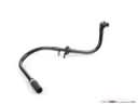 Toyota Prius Brake Booster Vacuum Hose
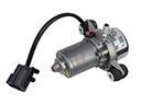 Toyota Prius Brake Booster Vacuum Pump
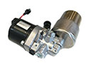 Toyota Prius Brake Fluid Pump
 Toyota Prius Brake Line
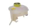 Toyota Prius Brake Master Cylinder Reservoir
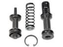 Toyota Prius Master Cylinder Repair Kit
 Toyota Prius Spindle Nut
 Toyota Prius Wheel Cylinder
 Toyota Prius Yaw Sensor