×
ToyotaParts- Hello
- Login or Register
- Quick Links
- Live Chat
- Track Order
- Parts Availability
- RMA
- Help Center
- Contact Us
- Shop for
- Toyota Parts
- Scion Parts
My Garage
My Account
Cart
OEM Toyota Prius Brake Booster
Brake Power Booster- Select Vehicle by Model
- Select Vehicle by VIN
Select Vehicle by Model
orMake
Model
Year
Select Vehicle by VIN
For the most accurate results, select vehicle by your VIN (Vehicle Identification Number).
1 Brake Booster found


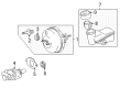
Toyota Prius Brake Booster Part Number: 44610-52051
$716.85 MSRP: $1050.56You Save: $333.71 (32%)Ships in 1-3 Business Days
Toyota Prius Brake Booster
Choose genuine Brake Booster that pass strict quality control tests. You can trust the top quality and lasting durability. Shopping for OEM Brake Booster for your Toyota Prius? Our website is your one-stop destination. We stock an extensive selection of genuine Toyota Prius parts. The price is affordable so you can save more. It only takes minutes to browse and find the exact fit. Easily add to cart and check out fast. Our hassle-free return policy will keep you stress-free. We process orders quickly for swift delivery. Your parts will arrive faster, so you can get back on the road sooner.
Toyota Prius Brake Booster Parts and Q&A
- Q: How to remove and reinstall the hydraulic brake booster assembly, including disconnecting brake lines, hoses, and connectors, and bleeding the brake system on Toyota Prius?A:The first step should be disabling the ignition switch and performing more than 40 brake pedal depressions because this step reduces power supply system pressure and enhances reaction force. High pressure should not deform the brake actuator tube and the ignition switch should stay off throughout the work process. Draw fluid using a syringe while keeping the brake fluid away from all painted areas. The work begins by removing the outer front cowl top panel followed by disconnecting the fluid level warning switch connector from the reservoir and removing the 2 bolts having a torque specification of 7.5 Nm (77 kgf-cm, 66 inch lbs.). Unfasten the hoses from the reservoir before removing it with the hoses. Then disconnect the hoses from the reservoir bracket clamp before you remove its 4 bracket fasteners which need a torque of 18 Nm (184 kgf-cm, 13 ft. lbs.). Detach the suction and liquid tubes while slipping off the retaining nut to free them. Disconnect the right front brake line from the flexible hose and 2 way using Special Service Tool: 09023-00100 and a spanner before torquing both connections to 15 Nm (155 kgf-cm, 11 ft. lbs.). Then pull out the brake line with grommet from the body. The brake line disconnected from the hydraulic brake booster assembly with the aid of Special Service Tool: 09023-00100, requiring torque to 15 Nm (155 kgf-cm, 11 ft. lbs.). The process of hydraulic brake booster assembly removal includes first disconnecting two connectors followed by unclasping the clamp while removing the clamp bracket and 3 bolts before releasing the wire harness and taking off the 3 installation bolts and a nut which required torque of 19 Nm (194 kgf-cm, 14 ft. lbs.) before completing removal of the hydraulic brake booster assembly and its 2 sub-bracket bolts requiring the same torque. The installation requires you to perform the removal steps backwards and then add brake fluid to the reservoir followed by brake system bleeding and testing for leaks.

Related Toyota Prius Parts
 Toyota Prius Brake Pads
 Toyota Prius Wheel Bearing
 Toyota Prius Brake Caliper
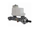 Toyota Prius Brake Master Cylinder
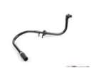 Toyota Prius Brake Booster Vacuum Hose
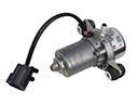 Toyota Prius Brake Booster Vacuum Pump
 Toyota Prius Brake Drum
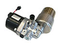 Toyota Prius Brake Fluid Pump
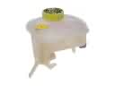 Toyota Prius Brake Master Cylinder Reservoir
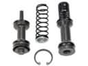 Toyota Prius Master Cylinder Repair Kit
 Toyota Prius Spindle Nut
 Toyota Prius Yaw Sensor