×
ToyotaParts- Hello
- Login or Register
- Quick Links
- Live Chat
- Track Order
- Parts Availability
- RMA
- Help Center
- Contact Us
- Shop for
- Toyota Parts
- Scion Parts
My Garage
My Account
Cart
OEM Toyota Yaris Brake Master Cylinder
- Select Vehicle by Model
- Select Vehicle by VIN
Select Vehicle by Model
orMake
Model
Year
Select Vehicle by VIN
For the most accurate results, select vehicle by your VIN (Vehicle Identification Number).
8 Brake Master Cylinders found


Toyota Yaris Master Cylinder Part Number: 47201-52320
$192.91 MSRP: $275.44You Save: $82.53 (30%)Ships in 1-3 Business Days
Toyota Yaris Master Cylinder Part Number: 47201-WB003
$209.02 MSRP: $298.44You Save: $89.42 (30%)Toyota Yaris Master Cylinder Part Number: 47201-WB001
$209.02 MSRP: $298.44You Save: $89.42 (30%)Ships in 1-3 Business Days
Toyota Yaris Master Cylinder Part Number: 47201-52620
$240.44 MSRP: $343.30You Save: $102.86 (30%)Ships in 1-3 Business DaysToyota Yaris Master Cylinder Part Number: 47201-52652
$256.91 MSRP: $366.80You Save: $109.89 (30%)Ships in 1-3 Business DaysToyota Yaris Master Cylinder Part Number: 47201-52642
$272.71 MSRP: $389.38You Save: $116.67 (30%)Ships in 1-3 Business Days
Toyota Yaris Master Cylinder Part Number: 47201-52330
$168.60 MSRP: $238.67You Save: $70.07 (30%)Toyota Yaris Master Cylinder Part Number: 47201-52600
$248.02 MSRP: $354.11You Save: $106.09 (30%)
Toyota Yaris Brake Master Cylinder
Choose genuine Brake Master Cylinder that pass strict quality control tests. You can trust the top quality and lasting durability. Shopping for OEM Brake Master Cylinder for your Toyota Yaris? Our website is your one-stop destination. We stock an extensive selection of genuine Toyota Yaris parts. The price is affordable so you can save more. It only takes minutes to browse and find the exact fit. Easily add to cart and check out fast. Our hassle-free return policy will keep you stress-free. We process orders quickly for swift delivery. Your parts will arrive faster, so you can get back on the road sooner.
Toyota Yaris Brake Master Cylinder Parts and Q&A
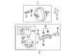
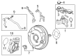
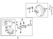
- Q: How to install the brake master cylinder on Toyota Yaris?A:Start installation of the brake master cylinder by inspecting and setting Special Service Tool: 09737-00013 against the master cylinder to access the brake booster push rod. Then adjust the push rod length until it touches the piston to finalize brake booster push rod adjustment. The brake master cylinder can be installed using the alternative tool: Special Service Tool: 09737-00012. The installation process requires measuring the tool clearance against the brake booster push rod with chalk on its flat tip by turning the tool upside down and ensuring the reading fits within -0.21 to 0 mm (-0.0083 to 0 in.) standard range. The rod length should be adjusted using Special Service Tool: 09737-00020 while holding it between the 7 mm socket driver and the tip of the rod then verify the clearance afterward. You should now install a new O-ring onto the brake master cylinder. When installing the brake master cylinder with ABS models use two nuts which require a torque setting of 13 Nm (127 kgf-cm, 9 ft-lbf). To install the brake master cylinder and brake tube way you must use the specified torque value for both models. Connect Special Service Tool: 09023-00100 to install the 2 brake tubes onto the brake master cylinder, deliver a torque of 15 Nm (155 kgf-cm, 11 ft-lbf) when using the tool and 14 Nm (143 kgf-cm, 10 ft-lbf) when using the tool, followed by confirming that the torque wrench lies at a 300 mm (11.81 in.) fulcrum length and runs parallel to the tool. To install brake tubes on brake tube ways of models without ABS employ Special Service Tool: 09023-00100 while applying necessary torque values. Complete the linkage between the brake fluid level warning switch and connect the clutch reservoir tube with its clip. The technician must first install the battery carrier and battery tray then add brake fluid to the reservoir before performing the master cylinder and Brake Line bleeding procedure and checking the fluid level alongside inspecting for any fluid leakages.
- Q: How to remove the brake master cylinder on Toyota Yaris?A:The first step to remove the brake master cylinder requires several brake pedal depressions to release vacuum from the booster followed by draining brake fluid while washing off paint-touching fluid. The first step requires the removal of the battery together with its tray and carrier. The clutch reservoir tube must be detached from manual transaxle cars by pulling down the clip. Detach the brake fluid warning connector of the ABS master cylinder sub-assembly before using the union nut wrench to disconnect the brake tubes and removing both nuts to extract the sub-assembly with its O-ring. Follow the original process for the version without ABS by separating brake tubes from the brake tube way. You should maintain delicate handling of the master cylinder to protect it from impact damage because it should never receive reuse if dropped. Horizontal orientation is essential for both the installation and removal of the sub-assembly while keeping the tip facing downwards prevents the piston from escaping. Also protect the piston from strikes and pinches. The master cylinder piston requires cleaning with a cloth before applying even layers of lithium soap-based glycol grease that needs to be placed on the piston's sliding part but should not include any different types of grease or fluid.


Related Toyota Yaris Parts
 Toyota Yaris Wheel Bearing
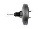 Toyota Yaris Brake Booster
 Toyota Yaris Wheel Hub
 Toyota Yaris Backing Plate
 Toyota Yaris Brake Drum
 Toyota Yaris Brake Line
 Toyota Yaris Brake Shoe Set
 Toyota Yaris Hydraulic Hose
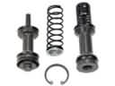 Toyota Yaris Master Cylinder Repair Kit
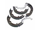 Toyota Yaris Parking Brake Shoes
 Toyota Yaris Wheel Cylinder
 Toyota Yaris Wheel Stud