×
ToyotaParts- Hello
- Login or Register
- Quick Links
- Live Chat
- Track Order
- Parts Availability
- RMA
- Help Center
- Contact Us
- Shop for
- Toyota Parts
- Scion Parts
My Garage
My Account
Cart
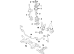
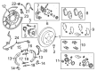
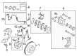
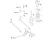
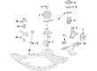
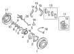
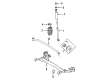
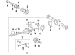
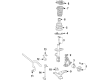
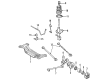
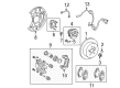
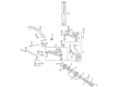
OEM Toyota Wheel Hub
Wheel Axle Hub- Select Vehicle by Model
- Select Vehicle by VIN
Select Vehicle by Model
orMake
Model
Year
Select Vehicle by VIN
For the most accurate results, select vehicle by your VIN (Vehicle Identification Number).
208 Wheel Hubs found


Toyota Hub Assembly Part Number: 43550-0R020
$283.78 MSRP: $405.18You Save: $121.40 (30%)Ships in 1-3 Business DaysProduct Specifications- Other Name: Hub&Bearing Assembly; Front Wheel Bearing & Hub; Wheel Hub Repair Kit; Axle Bearing; Front Hub & Bearing; Hub Sub-Assembly for Front Axle, Passenger & Driver Side; Wheel Bearing Assembly.
- Replaces: 43550-42020


Toyota Hub & Bearing Assembly, Rear Axle, Passenger Side Part Number: 42450-06090
$341.85 MSRP: $500.99You Save: $159.14 (32%)Ships in 1-3 Business DaysProduct Specifications- Other Name: Hub&Bearing Assembly, Rear Axle, Driver Side; Wheel Hub Repair Kit; Axle Bearing
- Position: Rear


Toyota Hub Assembly, Front Part Number: SU003-00782
$132.92 MSRP: $175.00You Save: $42.08 (25%)Ships in 1-3 Business DaysProduct Specifications- Other Name: Hub Unit Complete Front; Wheel Bearing & Hub Assembly; Wheel Hub Repair Kit; Axle Bearing; Front Hub & Bearing; Hub Sub-Assembly, Front Axle, Passenger & Driver Side; Wheel Bearing Assembly.
- Position: Front


Toyota Hub Assembly, Front Part Number: 43502-0E030
$130.65 MSRP: $184.95You Save: $54.30 (30%)Product Specifications- Other Name: Hub Sub-Assembly, Front Axle; Wheel Hub, Front; Front Hub & Bearing; Front Hub; Hub
- Position: Front
- Replaces: 43502-AA021, 43502-28100, 43502-08010, 43502-AA020


Toyota Hub & Bearing Assembly, Rear Axle, Passenger Side Part Number: 42450-06110
$344.80 MSRP: $505.32You Save: $160.52 (32%)Ships in 1 Business DayProduct Specifications- Other Name: Hub&Bearing Assembly, Rear Axle; Wheel Hub Repair Kit; Bearing; Axle Bearing
- Position: Passenger Side


Toyota Hub Assembly Part Number: 43550-47020
$309.65 MSRP: $442.10You Save: $132.45 (30%)Ships in 1-3 Business DaysProduct Specifications- Other Name: Hub&Bearing Assembly; Front Wheel Bearing & Hub; Bearing Module; Hub Repair Kit; Axle Bearing; Wheel Hub; Front Hub & Bearing; Hub Sub-Assembly, Front Axle, Passenger & Driver Side; Wheel Bearing Assembly.


Toyota Hub Assembly Part Number: 43550-0R010
$327.82 MSRP: $468.06You Save: $140.24 (30%)Ships in 1-2 Business DaysProduct Specifications- Other Name: Hub&Bearing Assembly; Front Wheel Bearing & Hub; Wheel Hub Repair Kit; Axle Bearing; Front Hub & Bearing; Hub Sub-Assembly, Front Axle, Passenger & Driver Side; Wheel Bearing Assembly.
- Replaces: 43550-42010


Toyota Hub & Bearing Assembly, Rear Axle, Passenger Side Part Number: 42450-60050
$344.80 MSRP: $505.32You Save: $160.52 (32%)Ships in 1 Business DayProduct Specifications- Other Name: Bearing Assembly, Rear Axle; Wheel Bearing & Hub; Repair Kit; Axle Bearing
- Position: Passenger Side
- Replaces: 42450-60060


Toyota Hub & Bearing, Rear Part Number: 42450-47030
$295.55 MSRP: $421.98You Save: $126.43 (30%)Ships in 1-3 Business DaysProduct Specifications- Other Name: Hub&Bearing Assembly, Rear Axle; Wheel Bearing & Hub Assembly; Wheel Hub Repair Kit; Axle Bearing.; Hub & Bearing Assembly; Rear Axle, Passenger & Driver Side; Wheel Bearing and Hub Assembly.
- Position: Rear


Toyota Bearing Housing, Driver Side Part Number: 42460-0C011
$347.97 MSRP: $496.83You Save: $148.86 (30%)Ships in 1 Business DayProduct Specifications- Other Name: Bearing Assembly, Rear Axle; Drive Axle Shaft Bearing, Rear Left; Wheel Bearing & Hub Assembly; Repair Kit; Hub & Bearing; Hub & Bearing Assembly, Rear Axle, Driver Side
- Position: Driver Side


Toyota Bearing Housing, Driver Side Part Number: 42460-60010
$344.80 MSRP: $505.32You Save: $160.52 (32%)Ships in 1-2 Business DaysProduct Specifications- Other Name: Bearing Assembly, Rear Axle; Wheel Bearing & Hub; Wheel Hub Repair Kit; Axle Bearing; Axle Bearings; Hub & Bearing; Hub & Bearing Assembly; Hub & Bearing Assembly, Rear Axle, Driver Side
- Position: Driver Side
- Replaces: 42460-60020

Toyota Hub & Bearing, Driver Side Part Number: 42460-06070
$344.80 MSRP: $505.32You Save: $160.52 (32%)Ships in 1-3 Business DaysProduct Specifications- Other Name: Hub&Bearing Assembly, Rear Axle; Rear Left Wheel Bearing & Hub; Wheel Hub Repair Kit; Axle Bearing; Hub & Bearing Assembly, Rear Axle, Driver Side; Wheel Bearing and Hub Assembly
- Position: Driver Side


Toyota Hub Sub-Assembly, Front Axle, Passenger Side Part Number: 43550-10010
$278.66 MSRP: $397.86You Save: $119.20 (30%)Ships in 1-3 Business DaysProduct Specifications- Other Name: Hub&Bearing Assembly; Front Axle, Driver Side; Wheel Hub Repair Kit
- Position: Front


Toyota Hub & Bearing Assembly, Rear Axle, Passenger Side Part Number: 42410-0E050
$333.29 MSRP: $475.87You Save: $142.58 (30%)Ships in 1-3 Business DaysProduct Specifications- Other Name: Hub&Bearing Assembly; Rear Axle, Driver Side; Wheel Hub Repair Kit; Wheel Bearing Kit; Axle Bearing
- Replaces: 42410-48041, 42410-0E021, 42410-48040


Toyota Bearing Housing, Passenger Side Part Number: 42450-0C011
$347.97 MSRP: $496.83You Save: $148.86 (30%)Ships in 1 Business DayProduct Specifications- Other Name: Bearing Assembly, Rear Axle; Drive Axle Shaft Bearing, Rear Right; Wheel Bearing & Hub Assembly; Hub Kit; Hub & Bearing; Hub & Bearing Assembly, Rear Axle, Passenger Side
- Position: Passenger Side


Toyota Hub & Bearing Part Number: 42410-08020
$375.67 MSRP: $550.55You Save: $174.88 (32%)Product Specifications- Other Name: Hub&Bearing Assembly; Rear Wheel Bearing and Hub Assembly; Wheel Hub Repair Kit; Axle Bearing.; Hub & Bearing Assembly; Rear Axle, Passenger & Driver Side; Wheel Bearing and Hub Assembly.


Toyota Hub Assembly, Front Part Number: 43503-69035
$368.52 MSRP: $540.07You Save: $171.55 (32%)Ships in 1 Business DayProduct Specifications- Other Name: Hub Sub-Assembly, Front Axle; Wheel Bearing and Hub Assembly, Front; Wheel Hub Repair Kit; Wheel Hub; Front Hub
- Position: Front
- Replaces: 43503-69015


Toyota Hub Assembly, Front Part Number: 43502-60201
$171.89 MSRP: $243.33You Save: $71.44 (30%)Ships in 1 Business DayProduct Specifications- Other Name: Hub Sub-Assembly, Front Axle; Wheel Hub, Front; Wheel Hub Repair Kit; Wheel Hub Assembly; Front Hub; Hub; Hub Sub-Assembly, Front Axle, Passenger Side; Hub Sub-Assembly, Front Axle, Driver Side; Wheel Hub
- Position: Front
- Replaces: 43502-60200, 43502-60180


Toyota Hub Assembly, Front Part Number: 43502-28090
$129.36 MSRP: $183.12You Save: $53.76 (30%)Ships in 1-3 Business DaysProduct Specifications- Other Name: Hub Sub-Assembly, Front Axle; Wheel Hub, Front; Front Hub; Hub; Hub Sub-Assembly, Front Axle, Passenger Side; Hub Sub-Assembly, Front Axle, Driver Side; Wheel Hub
- Manufacturer Note: (J)
- Position: Front
- Replaces: 43502-AA010, 43502-AA011


Toyota Hub & Bearing, Rear Part Number: 42450-02170
$413.13 MSRP: $605.44You Save: $192.31 (32%)Ships in 1-3 Business DaysProduct Specifications- Other Name: Hub&Bearing Assembly, Rear Axle; Wheel Bearing & Hub Assembly; Wheel Hub Repair Kit; Axle Bearing; Hub & Bearing Assembly, Rear Axle, Passenger Side; Driver Side; Wheel Bearing & Hub Assembly.
- Position: Rear
| Page 1 of 11 |Next >
1-20 of 208 Results
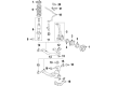
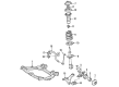
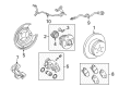
Toyota Wheel Hub
OEM parts deliver unmatched quality you can rely on. They pass extensive quality control inspections. Toyota produces them to the official factory specifications. This process helps prevent defects and imperfections. So you can get exceptional lifespan and a flawless fit. Need new OEM Toyota Wheel Hub? You'll love our wide selection of genuine options. Shop in minutes and skip the hunt. Our prices are unbeatable, you'll save time and money. It's easy to shop and find the right piece. Our committed customer service team gives professional help from start to finish. Every part includes a manufacturer's warranty. We ship quickly, your parts will arrive fast at your door.
Toyota Wheel Hub clamps the wheel and the axle but allows it to rotate freely to ensure a good grip and power. Toyota expanded in 1937 as a small firm that prides itself on being lean to 2010 as a corporate citizen manufacturing the world's dependable vehicles and honing assembly line with kaizen improvements day by day that have slenderized inventories and boosted morale in five continents. In 2022, Toyota enhanced its Hybrid Synergy Drive by combining electric power with fuel economy in numerous models between commuters and adventure seekers. The TNGA platform of Toyota redefined layouts, reduced the centers of gravity and handling that have sharpened it to leave drivers feeling relaxed even on rough lanes, not necessarily the test tracks. Toyota gained respect by showing that hybrids and traditional rigs have a lifespan of years and will still allow running costs to remain civil. Bearings and frequently brake rotor mounts are also located in Wheel Hub to provide the rotation in the right direction and prevent wobbling of tires. Once a Wheel Hub begins rumbling or the brake pedal begins pulsing, do not pay attention to it and risk the wheel locking halfway in the corner at highway speed. Installing a new Wheel Hub with new stud pattern, bearing spec prevents noise, reestablishes tracking and maintains power supply to pavement. A silent Wheel Hub translates to the ride being sincere and the steering being honest.
Toyota Wheel Hub Parts and Q&A
- Q: Should the Wheel Hub and Bearing Be Pressed from the Steering Knuckle by a Professional Shop on a Toyota Corolla?A:Because of the specific tools as well as experience needed in order to press the hub and bearing on to the steering knuckle, this should ideally be done at the mechanic's shop. However, due to the difficulties it might be necessary to remove the steering knuckle and hub, and take the assembly to an automobile mechanics shop that has equipment that is fitted for the removal process.
- Q: How to replace the Wheel Hub on 1995 through 2004 Toyota Tacoma?A:Remove the steering knuckle. The front hub and bearing are pressed into the steering knuckle on these models. Take the steering knuckle to an automotive machine shop to have the hub and old bearing pressed out and the new bearing and hub pressed in. Install the steering knuckle.


Related Toyota Parts
 Toyota Brake Pads
 Toyota Brake Caliper
 Toyota Speed Sensor
 Toyota Spindle Nut
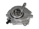 Toyota Vacuum Pump
 Toyota Brake Line
 Toyota Brake Booster Vacuum Hose
 Toyota Brake Booster Vacuum Pump
 Toyota Brake Caliper Bracket
 Toyota Brake Drum
 Toyota Brake Fluid Pump
 Toyota Brake Shoe Set
Browse Toyota Wheel Hub by Models
Tacoma 4Runner Camry Tundra Corolla RAV4 Highlander Prius Sienna Land Cruiser Pickup FJ Cruiser 86 Sequoia T100 Avalon Celica Supra Yaris Matrix MR2 Solara Venza GR86 Echo C-HR Cressida Grand Highlander Paseo Previa Prius C Prius Prime bZ4X Corolla Cross Corolla iM Crown Crown Signia GR Corolla Mirai MR2 Spyder Prius V Starlet Tercel Van Yaris iA Prius Plug-In GR Supra Prius AWD-e RAV4 Prime