×
ToyotaParts- Hello
- Login or Register
- Quick Links
- Live Chat
- Track Order
- Parts Availability
- RMA
- Help Center
- Contact Us
- Shop for
- Toyota Parts
- Scion Parts
My Garage
My Account
Cart
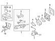
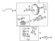
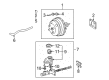
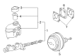
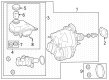
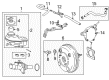
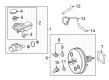
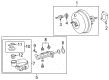
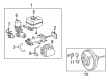
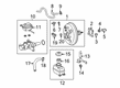
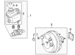
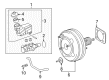
OEM Toyota Brake Master Cylinder Reservoir
Brake Fluid Storage Tank- Select Vehicle by Model
- Select Vehicle by VIN
Select Vehicle by Model
orMake
Model
Year
Select Vehicle by VIN
For the most accurate results, select vehicle by your VIN (Vehicle Identification Number).
77 Brake Master Cylinder Reservoirs found


Toyota Master Cylinder Reservoir Part Number: 47220-48220
$141.69 MSRP: $200.58You Save: $58.89 (30%)Ships in 1-3 Business DaysProduct Specifications- Other Name: Reservoir Assembly, Master Cylinder; Brake Master Cylinder Reservoir; Reservoir Assembly; Reservoir; Reservoir Sub-Assembly, Brake Master Cylinder; Reservoir Assembly, Brake Master Cylinder


Toyota Master Cylinder Reservoir Part Number: 47220-08030
$155.32 MSRP: $219.88You Save: $64.56 (30%)Ships in 1-3 Business DaysProduct Specifications- Other Name: Reservoir Assembly, Master Cylinder; Brake Master Cylinder Reservoir; Reservoir Assembly; Reservoir Sub-Assembly, Brake Master Cylinder


Toyota Reservoir Assembly Part Number: 47220-35040
$165.43 MSRP: $234.18You Save: $68.75 (30%)Product Specifications- Other Name: Reservoir Assembly, Master Cylinder; Brake Master Cylinder Reservoir; Reservoir Sub-Assembly, Brake Master Cylinder
- Manufacturer Note: W(ABS)


Toyota Master Cylinder Reservoir Part Number: 47220-0C022
$165.66 MSRP: $234.51You Save: $68.85 (30%)Product Specifications- Other Name: Reservoir Assembly, Master Cylinder; Brake Master Cylinder Reservoir; Reservoir Assembly; Reservoir Sub-Assembly, Brake Master Cylinder
- Replaces: 47220-0C021, 47220-0C020


Toyota Reservoir Part Number: 47220-42080
$142.75 MSRP: $202.07You Save: $59.32 (30%)Ships in 1-3 Business DaysProduct Specifications- Other Name: Reservoir Assembly, Master Cylinder; Reservoir Sub-Assembly, Brake Master Cylinder

Toyota Master Cylinder Part Number: 47220-19025
$123.48 MSRP: $174.80You Save: $51.32 (30%)Ships in 1-2 Business DaysProduct Specifications- Other Name: Reservoir Assembly, Master Cylinder; Reservoir Assembly; Reservoir Assembly, Brake Master Cylinder

Toyota Reservoir Assembly Part Number: 47220-02350
$119.54 MSRP: $169.23You Save: $49.69 (30%)Ships in 1-3 Business DaysProduct Specifications- Other Name: Reservoir Assembly, Master Cylinder; Brake Master Cylinder Reservoir; Reservoir Sub-Assembly, Brake Master Cylinder

Toyota Master Cylinder Reservoir Part Number: 47220-09220
$119.60 MSRP: $169.32You Save: $49.72 (30%)Ships in 1-3 Business DaysProduct Specifications- Other Name: Reservoir Set, Master; Brake Master Cylinder Reservoir; Reservoir Assembly; Reservoir Sub-Assembly, Brake Master Cylinder
Toyota Reservoir Assembly Part Number: 47220-02340
$123.25 MSRP: $174.47You Save: $51.22 (30%)Ships in 1-3 Business DaysProduct Specifications- Other Name: Reservoir Assembly, Master Cylinder; Brake Master Cylinder Reservoir; Reservoir Sub-Assembly, Brake Master Cylinder

Toyota Master Cylinder Reservoir Part Number: 47220-52280
$119.85 MSRP: $169.66You Save: $49.81 (30%)Ships in 1-3 Business DaysProduct Specifications- Other Name: Reservoir Assembly, Master Cylinder; Brake Master Cylinder Reservoir; Reservoir Assembly; Reservoir Sub-Assembly, Brake Master Cylinder; Reservoir Assembly, Brake Master Cylinder
Toyota Master Cylinder Reservoir Part Number: 47220-52270
$123.48 MSRP: $174.80You Save: $51.32 (30%)Ships in 1-3 Business DaysProduct Specifications- Other Name: Reservoir Assembly, Master Cylinder; Brake Master Cylinder Reservoir; Reservoir Assembly; Reservoir Sub-Assembly, Brake Master Cylinder; Reservoir Assembly, Brake Master Cylinder

Toyota Reservoir Part Number: 47220-42110
$119.85 MSRP: $169.66You Save: $49.81 (30%)Ships in 1-3 Business DaysProduct Specifications- Other Name: Reservoir Assembly, Master Cylinder; Brake Master Cylinder Reservoir; Reservoir Sub-Assembly, Brake Master Cylinder

Toyota Reservoir Sub-Assembly, Brake Master Cylinder Part Number: 47220-48200
$123.60 MSRP: $174.97You Save: $51.37 (30%)Ships in 1-3 Business DaysProduct Specifications- Other Name: Reservoir Assembly, Master Cylinder
Toyota Master Cylinder Reservoir Part Number: 47220-0R050
$119.96 MSRP: $169.82You Save: $49.86 (30%)Ships in 1-3 Business DaysProduct Specifications- Other Name: Reservoir Assembly, Master Cylinder; Brake Master Cylinder Reservoir; Reservoir Assembly; Reservoir; Reservoir Sub-Assembly, Brake Master Cylinder; Reservoir Assembly, Brake Master Cylinder

Toyota Master Cylinder Reservoir Part Number: 47220-0C060
$123.60 MSRP: $174.97You Save: $51.37 (30%)Ships in 1-3 Business DaysProduct Specifications- Other Name: Reservoir Assembly, Master Cylinder; Brake Master Cylinder Reservoir; Reservoir Assembly; Reservoir Sub-Assembly, Brake Master Cylinder

Toyota Master Cylinder Reservoir Part Number: 47220-06180
$123.60 MSRP: $174.97You Save: $51.37 (30%)Ships in 1-3 Business DaysProduct Specifications- Other Name: Reservoir Assembly, Master Cylinder; Brake Master Cylinder Reservoir; Reservoir Assembly; Reservoir Sub-Assembly, Brake Master Cylinder; Reservoir Assembly, Brake Master Cylinder
Toyota Master Cylinder Reservoir Part Number: 47220-04090
$119.96 MSRP: $169.82You Save: $49.86 (30%)Ships in 1-3 Business DaysProduct Specifications- Other Name: Reservoir Assembly, Master Cylinder; Brake Master Cylinder Reservoir; Reservoir; Reservoir Sub-Assembly, Brake Master Cylinder


Toyota Master Cylinder Reservoir Part Number: 47220-60130
$177.88 MSRP: $253.98You Save: $76.10 (30%)Product Specifications- Other Name: Reservoir Assembly, Master Cylinder; Reservoir Sub-Assembly, Brake Master Cylinder


Toyota Reservoir Assembly Part Number: 47220-08010
Product Specifications- Other Name: Reservoir Assembly, Master Cylinder; Brake Master Cylinder Reservoir; Reservoir Sub-Assembly, Brake Master Cylinder


Toyota Master Cylinder Reservoir Part Number: 47220-0C010
Product Specifications- Other Name: Reservoir Assembly, Master Cylinder; Brake Master Cylinder Reservoir; Reservoir Assembly; Reservoir Sub-Assembly, Brake Master Cylinder
| Page 1 of 4 |Next >
1-20 of 77 Results
Toyota Brake Master Cylinder Reservoir
OEM parts deliver unmatched quality you can rely on. They pass extensive quality control inspections. Toyota produces them to the official factory specifications. This process helps prevent defects and imperfections. So you can get exceptional lifespan and a flawless fit. Need new OEM Toyota Brake Master Cylinder Reservoir? You'll love our wide selection of genuine options. Shop in minutes and skip the hunt. Our prices are unbeatable, you'll save time and money. It's easy to shop and find the right piece. Our committed customer service team gives professional help from start to finish. Every part includes a manufacturer's warranty. We ship quickly, your parts will arrive fast at your door.
Toyota Brake Master Cylinder Reservoir makes brake fluid steady and pressurized to enable rapid and repeatable stopping power. Making lean Japanese origins, Toyota has become a global powerhouse by removing waste and letting factory teams fix glitches in real time. Consumers franchise Toyota due to the fact that its hybrids consume less fuel but remain sturdy with rough commutes and dusty back roads. Continuous redesigns of the platform such as TNGA provide Toyota models with lower center of gravity, sweeter steering, and enhanced crash protection. The past few years Toyota increased efforts to go plug-in, increasing the electric range of crossovers without adding curb weight. The company constructs the assembly lines in such a way that they halt whenever anomalies emerge, which requires quality to increase with each unit. Hybrid Synergy Drive releases have been implemented among sedans, SUVs, and even trucks such that buyers will enjoy the mileage without compromising speed. Brake Master Cylinder Reservoir prevents moisture from entering the hydraulic circuit to keep the fluid clear and maintain steady pressurization even when making hard stops and scorching summer events. It features hard nylon sides that shake off heat and vibration, which isolates fissures that would cause pressure bleed and increase the stretch distance. The Brake Master Cylinder Reservoir is equipped with two channels internally in case either of its lines bursts, the remaining Brake Master Cylinder Reservoir channel supplies the calipers to provide the driver with super-solid pedal action when needed.
Toyota Brake Master Cylinder Reservoir Parts and Q&A
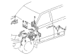
- Q: How to replace the Brake Master Cylinder Reservoir Sub-Assembly on Toyota Highlander?A:The first step to change the Brake Master Less Reservoir Tank Cylinder Sub-Assembly includes draining brake fluid while taking care it does not contact painted surfaces. Begin by removing the air cleaner assembly with hose and proceed to detach the front suspension brace sub-assy upper center through wire harness clamp and ABS R/B disconnection when needed followed by unfastening the four nuts on the brace. The brake fluid level warning switch connector needs removal along with potential actuator No. 1 hose detaching from the reservoir by sliding a clip. Use Special Service Tool: 09023-00100 to remove the 2 brake lines before taking out the check valve bracket and master cylinder sub-assy by removing its 2 nuts. You should also remove the brake master cylinder gasket and the reservoir tank stopper before pulling out the master cylinder reservoir sub-assy and removing the 2 grommets. Lithium soap base glycol grease should be applied to the new grommets before they are installed in the master cylinder reservoir sub-assy, followed by the complete assembly placement to the master cylinder. The reservoir tank stopper should be installed with proper fitment before applying a new gasket. When replacing the master cylinder use the accessory tool which requires chalk, place it against the brake booster to measure the push rod clearance and adjust using Special Service Tool: 09737-00020. Lock the master cylinder sub-assy and check valve bracket into place using 2 nuts that should be torqued up to 13 Nm (130 kgf-cm, 9 ft. lbs.). Then use Special Service Tool: 09023-00100 to torque the 2 brake lines to 15 Nm (155 kgf-cm, 11 ft. lbs.). The job requires reconnection of the actuator No. 1 hose followed by attaching the brake fluid level warning switch connector. Reinstall the front suspension brace sub-assy upper center using 4 nuts while torquing them to 80 Nm (815 kgf-cm, 59 ft. lbs.). Also reconnect wire harness clamps where needed. Reinstall the air filter system while attaching the hose before filling the brake fluid reservoir and bleeding master cylinder lines and brake tube. The procedure ends with checking the fluid level and inspecting the system for any fluid leakage.
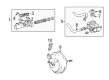
- Q: How to service and repair the Brake Master Cylinder Reservoir Sub-Assembly on Toyota Sienna?A:The service and repair process for Brake Master Less Reservoir Tank Cylinder Sub-Assembly starts with fluid drainage from braking systems followed by cleaning paint surfaces exposed to drained fluid. First disconnect the battery negative terminal followed by removal of the air cleaner assembly with hose and the cowl top panel sub-assembly outer front. It will then become necessary to disconnect the brake master cylinder using Special Service Tool: 09023-00100. The tool enables you to disconnect both brake tubes while sliding the clip to detach the reservoir hose and removing the two nuts. To access the brake master less reservoir tank cylinder sub-assembly securely position the brake master cylinder between soft-jawed vise and aluminum plates before removing the O-ring with a screwdriver. The brake tube requires Special Service Tool: 09023-00100 to disconnect for further detachment of two nuts and two bolts while removing the sub-assembly from its position. Drop the No.3 piston from the diameter converting unit and the No.1 piston from the plunger master cylinder because replacement parts cannot be used if these components fall. A pin punch of 5 mm diameter together with a hammer should be used to remove the pin before taking out the brake master cylinder union and two grommets. For brake master less reservoir tank cylinder sub-assembly installation you should apply lithium soap base glycol grease to the grommets then insert the master cylinder union with the pin while adding the two new O-rings. Fasten the sub-assembly with two nuts and two bolts while torquing them to 25 Nm (255 kgf-cm, 18 ft. lbs.) then check for proper installation of the No.3 piston without looseness. After connecting the brake tube to the brake master cylinder using Special Service Tool: 09023-00100 and torquing it to 15 Nm (155 kgf-cm, 11 ft. lbs.) install a new O-ring before continuing. Reinstall the brake master cylinder with two nuts and torques them to 13 Nm (130 kgf-cm, 9 ft. lbs.) but before doing so reconnect the reservoir hose then use Special Service Tool: 09023-00100 to restore connection of the two brake tubes which demands a torque of 15 Nm (155 kgf-cm, 11 ft. lbs.). Proceed with the following brake system installation steps by filling the reservoir with brake fluid, bleeding both the master cylinder and brake line followed by checking reservoir fluid level, examining for leakage, reattaching the cowl top panel front outer and inspecting brake pedal height. Finish by testing the brake actuator with a Toyota hand-held tester.


Related Toyota Parts
 Toyota Wheel Bearing
 Toyota Wheel Hub
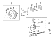
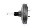 Toyota Brake Booster
 Toyota Brake Rotor
 Toyota Brake Proportioning Valve
 Toyota Vacuum Pump
 Toyota Brake Bleeder Screw
 Toyota Brake Booster Vacuum Pump
 Toyota Brake Caliper Bracket
 Toyota Brake Caliper Piston
 Toyota Brake Drum
 Toyota Yaw Sensor