×
ToyotaParts- Hello
- Login or Register
- Quick Links
- Live Chat
- Track Order
- Parts Availability
- RMA
- Help Center
- Contact Us
- Shop for
- Toyota Parts
- Scion Parts
My Garage
My Account
Cart
OEM Toyota Corolla Wheel Hub
Wheel Axle Hub- Select Vehicle by Model
- Select Vehicle by VIN
Select Vehicle by Model
orMake
Model
Year
Select Vehicle by VIN
For the most accurate results, select vehicle by your VIN (Vehicle Identification Number).
21 Wheel Hubs found


Toyota Corolla Hub Assembly Part Number: 43550-47020
$309.65 MSRP: $442.10You Save: $132.45 (30%)Ships in 1-3 Business Days

Toyota Corolla Hub & Bearing, Rear Part Number: 42450-02170
$413.13 MSRP: $605.44You Save: $192.31 (32%)Ships in 1-3 Business Days

Toyota Corolla Hub Assembly, Front Part Number: 43550-02090
$226.00 MSRP: $322.67You Save: $96.67 (30%)Ships in 1-3 Business Days

Toyota Corolla Hub & Bearing, Rear Part Number: 42450-01010
$528.44 MSRP: $774.44You Save: $246.00 (32%)Ships in 1-3 Business Days

Toyota Corolla Front Hub Part Number: 43502-12090
$144.04 MSRP: $203.91You Save: $59.87 (30%)Ships in 1-3 Business Days


Toyota Corolla Wheel Hub, Front Part Number: 43502-02080
$125.48 MSRP: $177.63You Save: $52.15 (30%)
Toyota Corolla Rear Hub & Bearing Part Number: 42450-02290
$268.75 MSRP: $383.72You Save: $114.97 (30%)Ships in 1-2 Business Days
Toyota Corolla Hub & Bearing, Rear Part Number: 42450-12170
$405.41 MSRP: $594.13You Save: $188.72 (32%)Ships in 1 Business Day

Toyota Corolla Hub & Bearing Assembly, Rear Axle, Passenger Side Part Number: 42450-76021
$268.99 MSRP: $384.05You Save: $115.06 (30%)Ships in 1-2 Business Days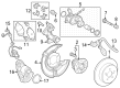
Toyota Corolla Rear Hub & Bearing Part Number: 42450-12231
$356.72 MSRP: $522.78You Save: $166.06 (32%)Ships in 1-2 Business Days
Toyota Corolla Hub Assembly Part Number: 42410-12090
$361.83 MSRP: $530.26You Save: $168.43 (32%)Ships in 1-3 Business Days
Toyota Corolla Hub Assembly Part Number: 42410-01020
$404.84 MSRP: $593.30You Save: $188.46 (32%)Ships in 1-3 Business DaysToyota Corolla Hub Assembly, Rear Part Number: 42450-02010
$487.24 MSRP: $714.06You Save: $226.82 (32%)Ships in 1-3 Business Days
Toyota Corolla Rear Hub & Bearing Part Number: 42450-02370
$328.40 MSRP: $468.88You Save: $140.48 (30%)Ships in 1-2 Business DaysToyota Corolla Hub Assembly, Rear Part Number: 42450-12211
$320.01 MSRP: $456.90You Save: $136.89 (30%)Ships in 1-2 Business Days
Toyota Corolla Hub Assembly, Rear Part Number: 42410-47030
$337.49 MSRP: $481.86You Save: $144.37 (30%)Ships in 1-3 Business Days

Toyota Corolla Front Hub Part Number: 43502-12070
$168.72 MSRP: $238.84You Save: $70.12 (30%)


Toyota Corolla Hub, Front Part Number: 43502-12110

Toyota Corolla Hub Assembly, Front Part Number: 43502-20110
$163.44 MSRP: $231.37You Save: $67.93 (30%)
Toyota Corolla Hub Assembly, Front Part Number: 43502-17010
| Page 1 of 2 |Next >
1-20 of 21 Results
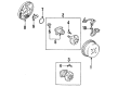
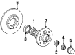
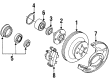
Toyota Corolla Wheel Hub
Choose genuine Wheel Hub that pass strict quality control tests. You can trust the top quality and lasting durability. Shopping for OEM Wheel Hub for your Toyota Corolla? Our website is your one-stop destination. We stock an extensive selection of genuine Toyota Corolla parts. The price is affordable so you can save more. It only takes minutes to browse and find the exact fit. Easily add to cart and check out fast. Our hassle-free return policy will keep you stress-free. We process orders quickly for swift delivery. Your parts will arrive faster, so you can get back on the road sooner.
Toyota Corolla Wheel Hub Parts and Q&A
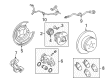
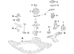
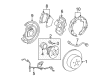
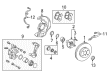
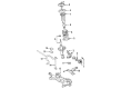
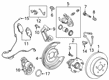
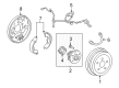
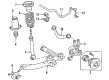
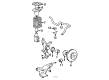
- Q: How to service and repair the Front Wheel Hub Sub-Assy LH on Toyota Corolla?A:Initialization of Front Wheel Hub Sub-Assy LH repairs requires users first to use Special Service Tool 09930-00010 for front wheel and front wheel hub LH nut removal. The front stabilizer link assembly LH along with the Speed Sensor front LH (with ABS) and front disc Brake Caliper assembly LH should be separated by unbolting them from the Steering Knuckle using two bolts for removal. First remove the front disc alongside the Special Service Tool called 09628-62011 for the tie rod end sub-assembly LH as well as the front suspension arm sub-assembly lower No.1 LH. Separate the front drive shaft assembly LH from the wheel hub using a plastic hammer before taking off the front wheel assembly LH but avoid damaging boot or speed sensor rotor during the process. Disassemble the front wheel assembly LH by rotating off the two bolts and two nuts and then free the lower Ball Joint assembly front LH through cotter pin and nut removal powered by Special Service Tool: 09628-62011. Utilize snap ring pliers to remove the front wheel hub LH hole snap ring followed by removing the front wheel hub sub-assembly LH using Special Service Tool 09520-00031 and then remove the inner hub bearing race from the hub sub-assembly LH using Special Service Tool 09950-40011 and its companion tools 09951-04020, and others. Remove the front wheel hub LH bearing by placing the inner race on the outer race followed by usage of Special Service Tool: 09223-15020, 09950-60010 (09951-00640), 09950-70010 (09951-07100, 09387-02010) and a press stand. Advance through these procedures to install the new hub LH bearing to the steering knuckle by using Special Service Tools: 09950-60020 (09951-00720), 09950-70010 (09951-07100) with a press followed by the dust cover front LH installation with three bolts torqued to 8.3 Nm (85 kgf-cm, 73 inch lbs.). The installation of front wheel hub sub-assembly LH requires Special Service Tools: 09608-32010, 09950-60010 (09951-00600), 09950-70010 (09951-07100) and a press for hub sub-assembly installation followed by a new LH hole snap ring installation with snap ring pliers. Fitting the lower ball joint assembly front LH requires tightening the nut to 103 Nm (1,050 kgf-cm, 76 ft. lbs.) and installing a new cotter pin while making sure the holes align properly or continuing to tighten the nut to 60 degrees. Use gentle force to push outward the front wheel assembly LH while aligning its spline part with the drive shaft assembly before insertion provided that both the outboard joint boot of the drive shaft and speed sensor rotor remain free from damage. Secure the front wheel assembly with two bolts to the Shock Absorber through two nuts by using engine oil on the screw parts of nuts and torquing them to 153 Nm (1,560 kgf-cm, 113 ft. lbs.). Connect the front suspension arm sub-assembly lower No.1 LH as well as the tie rod end sub-assembly LH and front stabilizer link assembly LH to the front disc and front disc brake caliper assembly LH while torquing the caliper assembly bolts to 107 Nm (1,089 kgf-cm, 79 ft. lbs.). A new hub LH nut needs installation using a 30 mm socket wrench then proper torquing up to 216 Nm (2,203 kgf-cm, 159 ft. lbs.). After applying the hammer and chisel to stake the LH nut, the process finishes with the front wheel installation at 103 Nm (1,050 kgf-cm, 76 ft. lbs.). Examine and correct the front wheel alignment together with an ABS speed sensor signal inspection (when ABS is present).
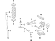
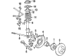
- Q: How to replace the front wheel hub on Toyota Corolla?A:Start the front wheel hub replacement process by taking out the front wheel along with the front axle hub LH nut using Special Service Tool 09930-00010. The front stabilizer link assembly LH together with the Speed Sensor front LH (with ABS) and front disc Brake Caliper assembly LH can be detached from the Steering Knuckle by taking out the two bolts. Using tool 09628-62011 during the process allows users to separate the tie rod end sub-assembly LH before moving on to the front suspension arm sub-assembly lower No.1 LH. Use a plastic hammer to detach the front drive shaft assembly LH from the axle hub but maintain protection of both the boot and the speed sensor rotor during this process. The front axle assembly LH can be removed first by releasing the two bolts and nuts. Next, separate the lower Ball Joint assembly front LH through nut and cotter pin removal while using Special Service Tool: 09628-62011. Begin the front axle hub LH disassembly process by removing its hole snap ring using snap ring pliers and subsequently taking out the front axle hub sub-assembly LH with Special Service Tool: 09520-00031 and to complete the operation remove the inner race of the LH hub bearing from the sub-assembly LH by utilizing Special Service Tool: 09950-40011 together with listed additional tools. To remove the front LH disc brake dust cover you must first detach its three bolts whereas to separate the front LH hub bearing you must position the inner race onto the outer race before using Special Service Tool: 09527-17011, 09950-60010, and a press. Insert the new hub LH bearing onto the steering knuckle by using Special Service Tool: 09950-60020 and operating a press before reinstalling the three bolted-down dust cover front LH with torques set at 8.3 Nm (85 kgf-cm, 73 inch lbs.). First, install the hub sub-assembly LH through Special Service Tool 09608-32010 and press. Afterwards install the new LH hole snap ring with snap ring pliers. Reinstall the lower ball joint assembly front LH by torquing the nut to 103 Nm (1,050 kgf-cm, 76 ft. lbs.) and adding a new cotter pin which should have holes properly aligned. Affix the front axle assembly LH to the Shock Absorber using two bolts and nuts while torquing them to 153 Nm (1,560 kgf-cm, 113 ft. lbs.) and apply engine oil to the screw parts when reusing nuts. Install the splined parts of the drive shaft assembly onto corresponding front axle assembly fittings while avoiding damage to the drive shaft outboard joint boot or speed sensor rotor. The installation process requires front suspension arm sub-assembly lower No.1 LH followed by tie rod end sub-assembly LH and front stabilizer link assembly LH as well as front disc and front disc brake caliper assembly LH to be torqued with 106.8 Nm (1,089 kgf-cm, 79 ft. lbs.). A socket wrench (30 mm) should be used to install the front axle hub LH nut which requires 216 Nm (2,203 kgf-cm, 159 ft. lbs.) torque before applying a chisel and hammer to stake the nut. Reinstall the front wheel followed by tightening it to 103 Nm while also checking the ABS speed sensor signal (with ABS). The inspection and adjustment of front wheel alignment completes the procedure.


Related Toyota Corolla Parts
 Toyota Corolla Wheel Bearing
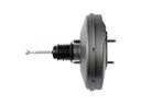 Toyota Corolla Brake Booster
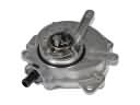 Toyota Corolla Vacuum Pump
 Toyota Corolla Wheel Stud
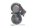 Toyota Corolla ABS Pump And Motor Assembly
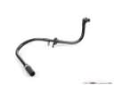 Toyota Corolla Brake Booster Vacuum Hose
 Toyota Corolla Brake Drum
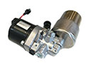 Toyota Corolla Brake Fluid Pump
 Toyota Corolla Hydraulic Hose
 Toyota Corolla Parking Brake Cable
 Toyota Corolla Spindle Nut
 Toyota Corolla Wheel Cylinder Repair Kit