×
ToyotaParts- Hello
- Login or Register
- Quick Links
- Live Chat
- Track Order
- Parts Availability
- RMA
- Help Center
- Contact Us
- Shop for
- Toyota Parts
- Scion Parts
My Garage
My Account
Cart
OEM 2005 Toyota Corolla Wheel Hub
Wheel Axle Hub- Select Vehicle by Model
- Select Vehicle by VIN
Select Vehicle by Model
orMake
Model
Year
Select Vehicle by VIN
For the most accurate results, select vehicle by your VIN (Vehicle Identification Number).
3 Wheel Hubs found


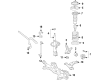
2005 Toyota Corolla Wheel Hub, Front
Part Number: 43502-02080$121.72 MSRP: $172.31You Save: $50.59 (30%)Product Specifications- Other Name: Hub Sub-Assembly, Front Axle; Wheel Hub, Front; Wheel Hub Repair Kit; Hub Assembly; Front Hub; Hub; Hub Sub-Assembly, Front Axle, Passenger Side; Hub Sub-Assembly, Front Axle, Driver Side
- Position: Front
- Replaces: 43502-32080, 43502-02100
- Item Weight: 4.30 Pounds
- Item Dimensions: 6.9 x 6.4 x 4.7 inches
- Condition: New
- Fitment Type: Direct Replacement
- SKU: 43502-02080
- Warranty: This genuine part is guaranteed by Toyota's factory warranty.


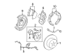
2005 Toyota Corolla Hub & Bearing, Rear
Part Number: 42450-01010$513.01 MSRP: $751.82You Save: $238.81 (32%)Ships in 1-3 Business DaysProduct Specifications- Other Name: Hub&Bearing Assembly, Rear Axle; Wheel Bearing & Hub Assembly; Wheel Hub Repair Kit; Axle Bearing; Hub & Bearing Assembly, Rear Axle, Passenger & Driver Side; Wheel Bearing and Hub Assembly.
- Position: Rear
- Replaces: 42450-02070
- Item Weight: 7.00 Pounds
- Item Dimensions: 6.8 x 6.8 x 6.2 inches
- Condition: New
- Fitment Type: Direct Replacement
- SKU: 42450-01010
- Warranty: This genuine part is guaranteed by Toyota's factory warranty.

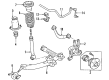
2005 Toyota Corolla Hub Assembly
Part Number: 42410-01020$393.04 MSRP: $576.01You Save: $182.97 (32%)Ships in 1-3 Business DaysProduct Specifications- Other Name: Hub&Bearing Assembly; Rear Wheel Bearing and Hub Assembly; Wheel Hub Repair Kit; Axle Bearing.; Hub & Bearing Assembly, Rear Axle, Passenger & Driver Side; Wheel Bearing and Hub Assembly.
- Replaces: 42410-20190, 42410-12260, 42410-02080
- Item Weight: 6.90 Pounds
- Item Dimensions: 7.0 x 6.8 x 5.5 inches
- Condition: New
- Fitment Type: Direct Replacement
- SKU: 42410-01020
- Warranty: This genuine part is guaranteed by Toyota's factory warranty.
2005 Toyota Corolla Wheel Hub
Looking for affordable OEM 2005 Toyota Corolla Wheel Hub? Explore our comprehensive catalogue of genuine 2005 Toyota Corolla Wheel Hub. All our parts are covered by the manufacturer's warranty. Plus, our straightforward return policy and speedy delivery service ensure an unparalleled shopping experience. We look forward to your visit!
2005 Toyota Corolla Wheel Hub Parts Q&A
- Q: How to service and repair the rear Wheel Hub and bearing assembly on the LH side on 2005 Toyota Corolla?A: The first step to work on the LH side rear wheel hub and bearing assembly is to unmount and discard the rear wheel. Seclude the rear disc brake caliper assembly LH through removal of its 2 bolts. For disc rear brake type cars remove the rear disc before proceeding to the drum rear brake type cars with their drum sub-assembly removal. First detach the ABS skid control sensor wire before removing the 4 bolts to uninstall the LH side rear wheel hub and bearing assembly. Use the 4 bolts to secure the new rear wheel hub and bearing assembly LH and torqued to 61 Nm (622 kgf-cm, 45 ft. lbs.). Secure the skid control sensor wire directly without twisting then check both the wheel hub bearing for proper fitment and eliminate runout. The repairs continue with the drum rear brake type brake drum sub-assembly installation then moving on to the rear disc installation for the disc rear brake type. Reattach the 2 bolts on the rear disc brake caliper assembly LH using 47 Nm (480 kgf-cm, 34 ft. lbs.) torque before installing the rear wheel with 103 Nm (1,050 kgf-cm, 76 ft. lbs.) torque. In the final step inspect the ABS speed sensor signal through the ABS system.
Related 2005 Toyota Corolla Parts
 2005 Toyota Corolla Wheel Bearing
 2005 Toyota Corolla Speed Sensor
 2005 Toyota Corolla Brake Caliper Bracket
 2005 Toyota Corolla Brake Proportioning Valve
 2005 Toyota Corolla Wheel Cylinder
 2005 Toyota Corolla Wheel Stud
 2005 Toyota Corolla Brake Booster Vacuum Hose
 2005 Toyota Corolla Brake Caliper Piston
 2005 Toyota Corolla Brake Disc
 2005 Toyota Corolla Master Cylinder Repair Kit
 2005 Toyota Corolla Parking Brake Cable
 2005 Toyota Corolla Yaw Sensor