×
ToyotaParts- Hello
- Login or Register
- Quick Links
- Live Chat
- Track Order
- Parts Availability
- RMA
- Help Center
- Contact Us
- Shop for
- Toyota Parts
- Scion Parts
My Garage
My Account
Cart
OEM Toyota MR2 Spyder Wheel Hub
Wheel Axle Hub- Select Vehicle by Model
- Select Vehicle by VIN
Select Vehicle by Model
orMake
Model
Year
Select Vehicle by VIN
For the most accurate results, select vehicle by your VIN (Vehicle Identification Number).
1 Wheel Hub found


Toyota MR2 Spyder Hub Assembly Part Number: 43550-17010
$303.47 MSRP: $433.29You Save: $129.82 (30%)Ships in 1-3 Business Days
Toyota MR2 Spyder Wheel Hub
Choose genuine Wheel Hub that pass strict quality control tests. You can trust the top quality and lasting durability. Shopping for OEM Wheel Hub for your Toyota MR2 Spyder? Our website is your one-stop destination. We stock an extensive selection of genuine Toyota MR2 Spyder parts. The price is affordable so you can save more. It only takes minutes to browse and find the exact fit. Easily add to cart and check out fast. Our hassle-free return policy will keep you stress-free. We process orders quickly for swift delivery. Your parts will arrive faster, so you can get back on the road sooner.
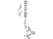
The Toyota MR2 Spyder Wheel Hub is one of the essential parts that illustrate the company's dependable and reliable automobiles. Known as the hub, the Wheel Hub is possibly the most critical linkage between the wheel and car since it enables rotation and holds the wheel firmly in place to guarantee the car's safety and steering; both which are critical for the Toyota MR2 Spyder. As one of the important components, it encloses production of wheel bearings and brake system improving work performance as well as safety. This product is produced for a wide range of Toyota models that are manufactured from 1999 to 2007; therefore, the Toyota MR2 Spyder Wheel Hub will suit anyone involved in these automobile models. It may look different with a different bolt pattern and a different Axle-Extension width; hence, it is relevant to choose the Perfect Wheel Hub for the certain type of MR2 Spyder. Notably, the Toyota MR2 Spyder Wheel Hub is made specifically for direct replacement, so the performance and durability of the automobile are maintained. Proper installation is important; that involves the use of torque to tighten bolts and avoid mechanical problems, in a way highlighting the importance of the Wheel Hub in maintaining the car's structure. The new product in the Wheel Hub category of Toyota is built with great strength and carefulness for the buyers in the automotive market, representing the soul of the Toyota MR2 Spyder and extending the car's success as a strong convertible sports car.
Toyota MR2 Spyder Wheel Hub Parts and Q&A
- Q: How to service and repair the wheel hub on Toyota MR2 Spyder?A:Service and repair operations on the wheel hub start by unwheeling and torqueing at 103 Nm (1,050 kgf-cm, 76 ft. lbs.). The next step is to remove the Brake Caliper and disc by detaching its 2 bolts which require a torque of 109 Nm (1,112 kgf-cm, 80 ft. lbs.) while securely supporting the brake caliper. A dial indicator shows the axle hub replacement is necessary when either measurement meets these specifications: the maximum backlash should not exceed 0.05 mm (0.0020 inch), and the maximum deviation at the surface of the axle hub outside the hub bolt should not exceed 0.07 mm (0.0028 inch). Begin the procedure by first removing the ABS speed sensor connector and afterward detach the front axle hub by unfastening the 4 bolts which require a torque of 56 Nm (571 kgf-cm, 41 ft. lbs.). Loosen the 2 Shock Absorber lower-side nuts to 140 Nm (1,430 kgf-cm) torque while keeping the bolts and nuts installed. The process to detach the lower suspension arm involves first removing its nut while stabilizing the suspension afterward using torques of 98 Nm (1,000 kgf-cm, 72 ft. lbs.) and secondly tightening the nut extra if new cotter pin holes do not align beyond 60°. Use Special Service Tool: 09620-62011 to perform suspension arm lower disconnect operations. The procedure to detach the tie rod end starts by removing its cotter pin and nut with a torque of 49 Nm (500 kgf-cm) and 36 ft. lbs. and extends to additional tightening of the nut beyond 60 degrees if the holes are misaligned during installation while utilizing Special Service Tool: 09610-20012. To complete the task remove the steering knuckle by first applying engine oil to the nuts' threads during installation and then take out the 2 bolts and 2 nuts from the shock absorber's lower side. The correct procedure for installation includes performing steps in the opposite order of disassembly; eventually, verify that the ABS speed sensor signals function properly along with proper front wheel alignment.

Related Toyota MR2 Spyder Parts
 Toyota MR2 Spyder Backing Plate
 Toyota MR2 Spyder Brake Caliper
 Toyota MR2 Spyder Brake Caliper Bracket
 Toyota MR2 Spyder Brake Caliper Piston
 Toyota MR2 Spyder Brake Line
 Toyota MR2 Spyder Brake Pads
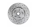 Toyota MR2 Spyder Brake Rotor
 Toyota MR2 Spyder Hydraulic Hose
 Toyota MR2 Spyder Speed Sensor
 Toyota MR2 Spyder Spindle Nut
 Toyota MR2 Spyder Wheel Bearing
 Toyota MR2 Spyder Wheel Stud