×
ToyotaParts- Hello
- Login or Register
- Quick Links
- Live Chat
- Track Order
- Parts Availability
- RMA
- Help Center
- Contact Us
- Shop for
- Toyota Parts
- Scion Parts
My Garage
My Account
Cart
OEM Toyota MR2 Spyder Wheel Bearing
Hub Bearing- Select Vehicle by Model
- Select Vehicle by VIN
Select Vehicle by Model
orMake
Model
Year
Select Vehicle by VIN
For the most accurate results, select vehicle by your VIN (Vehicle Identification Number).
3 Wheel Bearings found


Toyota MR2 Spyder Wheel Bearing Part Number: 90080-36136
$59.83 MSRP: $83.98You Save: $24.15 (29%)Ships in 1-3 Business Days


Toyota MR2 Spyder Hub Assembly Part Number: 43550-17010
$303.47 MSRP: $433.29You Save: $129.82 (30%)Ships in 1-3 Business Days

Toyota MR2 Spyder Axle Support Bearing Part Number: 90363-36004
$37.87 MSRP: $52.71You Save: $14.84 (29%)Ships in 1-3 Business Days
Toyota MR2 Spyder Wheel Bearing
Choose genuine Wheel Bearing that pass strict quality control tests. You can trust the top quality and lasting durability. Shopping for OEM Wheel Bearing for your Toyota MR2 Spyder? Our website is your one-stop destination. We stock an extensive selection of genuine Toyota MR2 Spyder parts. The price is affordable so you can save more. It only takes minutes to browse and find the exact fit. Easily add to cart and check out fast. Our hassle-free return policy will keep you stress-free. We process orders quickly for swift delivery. Your parts will arrive faster, so you can get back on the road sooner.
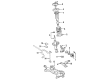
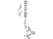
The Wheel Bearing has simple structure but a very critical part of the Toyota MR2 Spyder vehicles as it boosts their performance and safety massively. Popular for its durability, this Wheel Bearing helps in the rotation of the wheels in the least cause of friction and therefore serves as a goede part of the wheel and the tire system. The Toyota MR2 Spyder has the three different hub and bearing types but the most used is the integral hub and bearing assembly which usually integrated with the ABS sensor, and in the case of a defective hub and bearing assembly, it can be replaced as a single assembly. This design not only makes the maintenance easier but also provides longer and efficient performance of the car, which is Toyota MR2 Spyder. Also, some configurations of the system employ non-driven axle hubs with replaceable tapered roller bearings, which enable inspecting and replacing them to maintain Wheel Bearing's integrity. Some of the factors that require regular checks include noise, vibration, and roughness since worn-out Wheel Bearings can be deadly; a wheel may fall off in some circumstances. Recognized as a sports car, the Toyota MR2 Spyder manufactured between 1999 and 2007 focused on a light weight and a excellent handling; thus, the performance of its Wheel Bearing becomes even more valuable. Given that this Toyota MR2 Spyder Wheel Bearing is compatible with almost all the models of this sporty automobile, it avails itself as a solution that boosts the efficiency and safety of this automobile in equal measures so that the drivers of the Toyota MR2 Spyder can easily experience the awesome feeling that this automobile gives to those who ride it.
Toyota MR2 Spyder Wheel Bearing Parts and Q&A
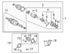
- Q: How to Service and Repair a Wheel Bearing on Toyota MR2 Spyder?A:You can start servicing wheel bearings after removing the rear wheel then torque to 103 Nm (1,050 kgf-cm, 76 ft. lbs.). Inspect the bearing backlash and measure axle hub deviation by supporting the Brake Caliper during this process until you reach the dial indicator's maximum allowable limit of 0.05 mm (0.0020 inch) near the center point of the axle hub. Excessive values require new bearing replacement. The surface of the axle hub needs to be checked outside the hub bolt for deviation that should not exceed 0.07 mm (0.0028 inch). If the measurement is beyond the limit, replace the axle hub. Install the disc and brake caliper through the fixing of their two bolts until they reach a torque of 59 Nm (602 kgf-cm, 44 ft. lbs.). Feed the drive shaft lock nut through Special Service Tool: 09930-00010 and hit it with a hammer to unstake the nut before removing it under braking conditions and torquing it to 216 Nm (2,200 kgf-cm, 159 ft. lbs.). Replacement of the lock nut is required for installation. First detach the brake caliper while removing its 2 bolts and securing it before removing the ABS speed sensor with bolt and sensor by using 8.0 Nm (82 kgf-cm, 71 inch lbs.) torque for the bolt and then 5.0 Nm (51 kgf-cm, 44 inch lbs.) torque for the wire harness clamp bolt on the axle carrier. The Shock Absorber's lower side nuts should be slightly loosened to 173 Nm (1,765 kgf-cm, 128 ft. lbs.) without removing either of the nuts or bolts. Disconnect the strut rod through removal of the bolt and nut from the rear axle carrier that requires 78 Nm (796 kgf-cm, 58 ft. lbs.) torque. Avoid turning the nut during removal and restore suspension stability before installing the bolt. Depart the No. 1 lower suspension arm into service by taking off the bolt and nut from the rear axle carrier where torques reach 103 Nm (1,051 kgf-cm, 76 ft. lbs.). Maintain safe suspension positioning when torquing both bolt and nut. Disconnection of the No. 2 lower suspension arm requires a removal of its torqued nut at 49 Nm (500 kgf-cm, 36 ft. lbs.) followed by using new nut installation and achieving torques post-suspension stabilization through the tool 09610-20012. The drive shaft must be disconnected at the axle hub while using a plastic hammer to protect both the boot and ABS speed sensor rotor. The procedure to remove the axle carrier with axle hub includes 2 bolts and 2 nuts and 4 washers located at the shock absorber's lower side followed by applying engine oil to the nut threads prior to installation before performing the carrier hub removal in a cautious manner to protect the boot and ABS speed sensor rotor. The procedure of installation reverses the removal sequence and a post-installation check should verify that the ABS speed sensor signals function properly while inspecting rear wheel alignment.

Related Toyota MR2 Spyder Parts
 Toyota MR2 Spyder Backing Plate
 Toyota MR2 Spyder Brake Caliper
 Toyota MR2 Spyder Brake Caliper Bracket
 Toyota MR2 Spyder Brake Caliper Piston
 Toyota MR2 Spyder Brake Line
 Toyota MR2 Spyder Brake Pads
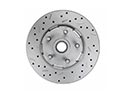 Toyota MR2 Spyder Brake Rotor
 Toyota MR2 Spyder Hydraulic Hose
 Toyota MR2 Spyder Speed Sensor
 Toyota MR2 Spyder Wheel Cylinder Repair Kit
 Toyota MR2 Spyder Wheel Hub
 Toyota MR2 Spyder Wheel Stud