×
ToyotaParts- Hello
- Login or Register
- Quick Links
- Live Chat
- Track Order
- Parts Availability
- RMA
- Help Center
- Contact Us
- Shop for
- Toyota Parts
- Scion Parts
My Garage
My Account
Cart
OEM 2002 Toyota MR2 Spyder Wheel Bearing
Hub Bearing- Select Vehicle by Model
- Select Vehicle by VIN
Select Vehicle by Model
orMake
Model
Year
Select Vehicle by VIN
For the most accurate results, select vehicle by your VIN (Vehicle Identification Number).
3 Wheel Bearings found


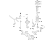
2002 Toyota MR2 Spyder Wheel Bearing
Part Number: 90080-36136$58.54 MSRP: $81.49You Save: $22.95 (29%)Ships in 1-3 Business DaysProduct Specifications- Other Name: Bearing, Radial Ball; Wheel Bearing, Front, Front Left, Front Right, Rear; Wheel Bearing Kit; Wheel Bearings; Front Wheel Bearing for Passenger & Driver Side Axle Hub.
- Replaces: 90363-40069, 90363-40066
- Item Weight: 2.00 Pounds
- Item Dimensions: 3.4 x 3.5 x 2.0 inches
- Condition: New
- Fitment Type: Direct Replacement
- SKU: 90080-36136
- Warranty: This genuine part is guaranteed by Toyota's factory warranty.


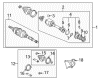
2002 Toyota MR2 Spyder Axle Support Bearing
Part Number: 90363-36004$36.67 MSRP: $51.05You Save: $14.38 (29%)Ships in 1-3 Business DaysProduct Specifications- Other Name: Bearing, Radial Ball; CV Axle Shaft Carrier Bearing, Front, Rear; Wheel Bearing; Axle Bearing; Inner Shaft Bearing; Case Bearing; Bearing; Bearing (For Front Drive Shaft); Bearing(For Rear Drive Shaft)
- Item Weight: 1.10 Pounds
- Item Dimensions: 2.8 x 0.9 x 2.9 inches
- Condition: New
- Fitment Type: Direct Replacement
- SKU: 90363-36004
- Warranty: This genuine part is guaranteed by Toyota's factory warranty.


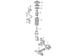
2002 Toyota MR2 Spyder Hub Assembly
Part Number: 43550-17010$303.47 MSRP: $433.29You Save: $129.82 (30%)Ships in 1-3 Business DaysProduct Specifications- Other Name: Hub&Bearing Assembly; Front Wheel Bearing & Hub; Wheel Hub Repair Kit; Axle Bearing; Front Hub & Bearing; Hub Sub-Assembly, Front Axle, Passenger & Driver Side; Wheel Bearing Assembly.
- Item Weight: 6.70 Pounds
- Item Dimensions: 6.8 x 6.8 x 6.4 inches
- Condition: New
- Fitment Type: Direct Replacement
- SKU: 43550-17010
- Warranty: This genuine part is guaranteed by Toyota's factory warranty.
2002 Toyota MR2 Spyder Wheel Bearing
Looking for affordable OEM 2002 Toyota MR2 Spyder Wheel Bearing? Explore our comprehensive catalogue of genuine 2002 Toyota MR2 Spyder Wheel Bearing. All our parts are covered by the manufacturer's warranty. Plus, our straightforward return policy and speedy delivery service ensure an unparalleled shopping experience. We look forward to your visit!
2002 Toyota MR2 Spyder Wheel Bearing Parts Q&A
- Q: How to service and repair the wheel bearing and ABS speed sensor on 2002 Toyota MR2 Spyder?A: The ABS speed sensor requires disassembly through pin punch removal of two pins with a hammer followed by the use of Service Tool: 09520-00031 (09520-00040, 09521-00020) to detach the sensor attachments. Anchor the axle hub assembly within a soft jaw vise where replacement operations should occur if any impact creates intense force to the assembly. Remove the ABS speed sensor using Special Service Tool: 09520-00031 (09520-00040, 09521-00020), 09950-00020, and 2 bolts (Diameter: 12 mm, Pitch: 1.5 mm). The sensor should be extracted straight out to prevent damage while avoiding foreign material on the sensor rotor. The axle hub assembly requires replacement when the sensor rotor shows damage and one must avoid scratching both the speed sensor and its contacting hub assembly surface. The contacting surfaces must be cleaned on both the hub and new ABS speed sensor before installing the sensor with its connector below the hub. You should use the Special Service Tools' 09527-10011, 09710-04101, 09950-60020 and its alternative 09951-00680 alongside a press for installing the new ABS speed sensor. Follow this procedure by checking for foreign matter and pressing it in slowly.
Related 2002 Toyota MR2 Spyder Parts
 2002 Toyota MR2 Spyder Backing Plate
 2002 Toyota MR2 Spyder Brake Caliper Bracket
 2002 Toyota MR2 Spyder Brake Caliper Piston
 2002 Toyota MR2 Spyder Brake Disc
 2002 Toyota MR2 Spyder Brake Line
 2002 Toyota MR2 Spyder Brake Pad Set
 2002 Toyota MR2 Spyder Hydraulic Hose
 2002 Toyota MR2 Spyder Speed Sensor
 2002 Toyota MR2 Spyder Wheel Cylinder
 2002 Toyota MR2 Spyder Wheel Cylinder Repair Kit
 2002 Toyota MR2 Spyder Wheel Hub
 2002 Toyota MR2 Spyder Wheel Stud