×
ToyotaParts- Hello
- Login or Register
- Quick Links
- Live Chat
- Track Order
- Parts Availability
- RMA
- Help Center
- Contact Us
- Shop for
- Toyota Parts
- Scion Parts
My Garage
My Account
Cart
OEM 2001 Toyota MR2 Spyder Wheel Bearing
Hub Bearing- Select Vehicle by Model
- Select Vehicle by VIN
Select Vehicle by Model
orMake
Model
Year
Select Vehicle by VIN
For the most accurate results, select vehicle by your VIN (Vehicle Identification Number).
3 Wheel Bearings found


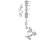
2001 Toyota MR2 Spyder Wheel Bearing
Part Number: 90080-36136$58.54 MSRP: $81.49You Save: $22.95 (29%)Ships in 1-3 Business DaysProduct Specifications- Other Name: Bearing, Radial Ball; Wheel Bearing, Front, Front Left, Front Right, Rear; Wheel Bearing Kit; Wheel Bearings; Front Wheel Bearing for Passenger & Driver Side Axle Hub.
- Replaces: 90363-40069, 90363-40066
- Item Weight: 2.00 Pounds
- Item Dimensions: 3.4 x 3.5 x 2.0 inches
- Condition: New
- Fitment Type: Direct Replacement
- SKU: 90080-36136
- Warranty: This genuine part is guaranteed by Toyota's factory warranty.


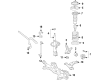
2001 Toyota MR2 Spyder Axle Support Bearing
Part Number: 90363-36004$36.67 MSRP: $51.05You Save: $14.38 (29%)Ships in 1-3 Business DaysProduct Specifications- Other Name: Bearing, Radial Ball; CV Axle Shaft Carrier Bearing, Front, Rear; Wheel Bearing; Axle Bearing; Inner Shaft Bearing; Case Bearing; Bearing; Bearing (For Front Drive Shaft); Bearing(For Rear Drive Shaft)
- Item Weight: 1.10 Pounds
- Item Dimensions: 2.8 x 0.9 x 2.9 inches
- Condition: New
- Fitment Type: Direct Replacement
- SKU: 90363-36004
- Warranty: This genuine part is guaranteed by Toyota's factory warranty.


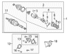
2001 Toyota MR2 Spyder Hub Assembly
Part Number: 43550-17010$303.47 MSRP: $433.29You Save: $129.82 (30%)Ships in 1-3 Business DaysProduct Specifications- Other Name: Hub&Bearing Assembly; Front Wheel Bearing & Hub; Wheel Hub Repair Kit; Axle Bearing; Front Hub & Bearing; Hub Sub-Assembly, Front Axle, Passenger & Driver Side; Wheel Bearing Assembly.
- Item Weight: 6.70 Pounds
- Item Dimensions: 6.8 x 6.8 x 6.4 inches
- Condition: New
- Fitment Type: Direct Replacement
- SKU: 43550-17010
- Warranty: This genuine part is guaranteed by Toyota's factory warranty.
2001 Toyota MR2 Spyder Wheel Bearing
Looking for affordable OEM 2001 Toyota MR2 Spyder Wheel Bearing? Explore our comprehensive catalogue of genuine 2001 Toyota MR2 Spyder Wheel Bearing. All our parts are covered by the manufacturer's warranty. Plus, our straightforward return policy and speedy delivery service ensure an unparalleled shopping experience. We look forward to your visit!
2001 Toyota MR2 Spyder Wheel Bearing Parts Q&A
- Q: How to Service and Repair a Wheel Bearing on 2001 Toyota MR2 Spyder?A: The wheel bearing servicing and repair starts with removing the front wheel which requires 103 Nm (1,050 kgf-cm, 76 ft.lb.) torque setting. Spin out the brake caliper and disc while unfastening the 2 bolts which require tightening to 109 Nm (1,112 kgf-cm, 80 ft. lbs.). Then securely fix the brake caliper in place. The dial indicator should test bearing backlash at the middle of the axle hub with a maximum permissible backlash of 0.05 mm (0.0020 inch). Replace the axle hub when backlash exceeds this limit. The allowable surface deviation measurement of the axle hub outside the hub bolts must be less than 0.07 mm (0.0028 inch) or the axle hub needs replacement. Separate the ABS speed sensor connector before removing the front axle hub by unscreving its 4 retaining bolts applying 56 Nm of torque. (571 kgf-cm, 41 ft. lbs.). Loosen the lower shock absorber nuts to 140 Nm torque yet don't untighten the 2 bolts and 2 nuts. The technician must stabilize the suspension before torquing the nut in step; keeping in mind extra tightening up to sixty degrees if the holes for new cotter pins are misaligned. The lower suspension arm disconnects using Special Service Tool: 09620 62011. To detach the tie rod end first remove the nut and cotter pin using 49 Nm (500 kgf-cm) torque until the holes realign for the new cotter pin during installation; extend the nut torque up to 60° if necessary. Use Special Service Tool: 09610-20012. During shock absorber lower side bolt and nut removal to access the steering knuckle you must coat engine oil on the nut threads. The installation procedure should be done in reverse order of removal while checking ABS speed sensor signals together with front wheel alignment.
Related 2001 Toyota MR2 Spyder Parts
 2001 Toyota MR2 Spyder Backing Plate
 2001 Toyota MR2 Spyder Brake Caliper Bracket
 2001 Toyota MR2 Spyder Brake Caliper Piston
 2001 Toyota MR2 Spyder Brake Disc
 2001 Toyota MR2 Spyder Brake Line
 2001 Toyota MR2 Spyder Brake Pad Set
 2001 Toyota MR2 Spyder Hydraulic Hose
 2001 Toyota MR2 Spyder Speed Sensor
 2001 Toyota MR2 Spyder Wheel Cylinder
 2001 Toyota MR2 Spyder Wheel Cylinder Repair Kit
 2001 Toyota MR2 Spyder Wheel Hub
 2001 Toyota MR2 Spyder Wheel Stud