- Hello
- Login or Register
- Quick Links
- Live Chat
- Track Order
- Parts Availability
- RMA
- Help Center
- Contact Us
- Shop for
- Toyota Parts
- Scion Parts

Popular OEM Toyota MR2 Spyder Parts
- Body & Hardware Parts View More >
- Electrical Parts View More >
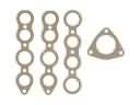
- Engine Parts View More >
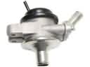
- Air & Fuel Delivery Parts View More >
- Belts & Cooling Parts View More >
- Steering Parts View More >
- Suspension Parts View More >
- Emission Control & Exhaust Parts View More >
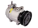
- A/C & Heating Parts View More >
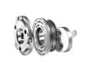
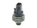
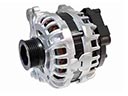
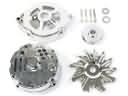
- Charging & Starting Parts View More >
- Brakes Parts View More >
- Transmission Parts View More >


Why Buy Genuine Toyota MR2 Spyder Parts From ToyotaPartsNow.com
ToyotaPartsNow.com highlights the reliability of OEM Toyota MR2 Spyder parts right at your fingertips. Our skilled staff assists customers in selecting the right Toyota MR2 Spyder parts and provides expert help with any unique part requests. At ToyotaPartsNow.com, we make all Toyota MR2 Spyder parts available to you quickly and efficiently through our fast order and reliable ship process. Our service is designed to make finding the correct Toyota MR2 Spyder parts fast and easy whether you are an amateur or a professional. We offer access to a broad inventory that includes a wide range of Toyota years and variants. Affordable prices, quick processing and professional service are also our specialty to ensure your car remains in top condition with OEM Toyota MR2 Spyder parts. You can feel confident shopping with us because all Toyota MR2 Spyder parts, such as Headlights & Lighting you purchase from our store are of genuine quality and built to last.
During its production period from 1999 to 2007 the Toyota MR2 Spyder gained recognition as a MR2 series variant because of its mid-engine rear-wheel-drive layout which highlighted driving performance characteristics. The powertrain of the Toyota MR2 Spyder comes from a 1.8 L 1ZZ-FED I4 engine able to produce 138 bhp at 6,400 rpm and 126 lb-ft of torque at 4,400 rpm which results in a balanced performance distribution. The Toyota MR2 Spyder maintains its responsiveness through lightweight structure which brings the curb weight to 2,195 lbs. The vehicle offers three transmission choices including a 5-speed manual, a 6-speed manual alongside a 2002-introduced 5-speed sequential manual transmission (SMT) that enables automatic gear shifts through either the gearstick or steering wheel buttons. The electro-hydraulic clutch system makes driving more enjoyable through automatic clutch operation thus improving the vehicle's control dynamics. The Toyota MR2 Spyder reaches its premier stability and control levels through its 96.5-inch wheelbase length and its dimensions of 153 inches in length and 66.7 inches in width and 48.8 inches in height. Production of the Toyota MR2 Spyder emphasized both reliability and performance making it an important model for the Toyota vehicle collection. The required maintenance for preserving vehicle structural integrity can be found through genuine Toyota MR2 Spyder parts that follow original factory standards.
The Toyota MR2 Spyder suffers from some mechanical issues that tend to affect the car's performance. A typical issue is high oil consumption that is usually caused by not changing the Toyota MR2 Spyder oil as frequently which causes engine sludge and excessive wearing piston rings. This issue impacts the engine, and drivers might encounter the oil light coming on. The frequent change of oil every 3,000 miles can help avoid this scenario. The timing chain and sprocket set are also another cause of concern, and they can fail or have problems due to the variable valve timing system (VVT-i). The Toyota MR2 Spyder engine digression may also cause this, leading to a slowdown in performance. Finally the Toyota MR2 Spyder can have issues related to rough idling and backfiring which is usually noted by a check engine light. This symptom is related to valve-related problems, as soft seats on engine valves could result in burned valves, up to misfiring. This would be an expensive internal engine repair for the Toyota MR2 Spyder operation, in that the cylinder head would need a complete rebuilding. Regularly checking the valve clearances every 40,000 miles can help reduce this problem. All these concerns make it apparent that regular maintenance of the Toyota MR2 Spyder parts is required to maximize the performance and lifespan of the engine.
Toyota MR2 Spyder Parts and Q&A
- Q: How to remove and install the timing chain on Toyota MR2 Spyder?A:Drain coolant; remove covers, belt/idler; support engine. Remove coils, head cover; set No.1 to TDC. Using specified SSTs, remove crank pulley, tensioner, water pump, cover, chain. Inspect: chain less than or equal to 122.6 mm; slipper/damper wear less than or equal to 1.0 mm; check sprockets/idler/tensioner. Replace seals/bearings. Reassemble with oil/sealant, align marks/torque, set tension, refill, check leaks.
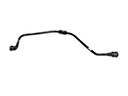
- Q: How to service and repair the power steering pump on Toyota MR2 Spyder?A:To service and repair the power steering pump, remove the reservoir cap, reservoir, and O-ring. Take out the rear housing, oil strainer, cam ring, vane pump rotor, and plates. Inspect components for specifications, check the flow control valve, and replace parts as needed. Reassemble with coated O-rings and secure all components.
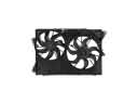
- Q: How to remove and reinstall a radiator on Toyota MR2 Spyder?A:Drain coolant. Remove trim, then radiator: detach bolts/nuts, carrier extensions, fan connectors, hoses, supports/bushings; remove fan. Disassemble with SST 09230-01010 (B 0.2-0.3 mm); uncaulk, remove tank/O-rings; max two recaulkings. Reassemble with SSTs 09230-01010/09231-14010 (8.4 mm; height 7.4-7.8 mm). Leak-test 177 kPa. Reinstall, torque fan/supports/extensions 5/12.5/8 Nm; refill.


