×
ToyotaParts- Hello
- Login or Register
- Quick Links
- Live Chat
- Track Order
- Parts Availability
- RMA
- Help Center
- Contact Us
- Shop for
- Toyota Parts
- Scion Parts
My Garage
My Account
Cart
OEM Toyota MR2 Spyder Alternator
Generator- Select Vehicle by Model
- Select Vehicle by VIN
Select Vehicle by Model
orMake
Model
Year
Select Vehicle by VIN
For the most accurate results, select vehicle by your VIN (Vehicle Identification Number).
1 Alternator found

Toyota MR2 Spyder Alternator Part Number: 27060-22040-84
$155.11 MSRP: $204.17You Save: $49.06 (25%)Ships in 1-3 Business Days
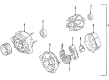
Toyota MR2 Spyder Alternator
Choose genuine Alternator that pass strict quality control tests. You can trust the top quality and lasting durability. Shopping for OEM Alternator for your Toyota MR2 Spyder? Our website is your one-stop destination. We stock an extensive selection of genuine Toyota MR2 Spyder parts. The price is affordable so you can save more. It only takes minutes to browse and find the exact fit. Easily add to cart and check out fast. Our hassle-free return policy will keep you stress-free. We process orders quickly for swift delivery. Your parts will arrive faster, so you can get back on the road sooner.
This alternator is an important part of the vehicle that speaks of Toyota MR2 Spyder's reliability and its desire to perform. Altogether, the alternator works as battery charger and electrical generator which directly converts mechanical energy provided by the engine into the electrical energy thus guaranteeing the work of MR2 Spyder's electrical systems and improving overall efficiency and security. The automotive alternator of the Toyota MR2 Spyder has a two-piece cast aluminium cover and comprises a stator and rotor that produce voltage and hence is crucial to the car's electrical system. Applicable for MR2 Spyder models manufactured from 1999 to 2007, and equipped with the 1.8 L 1ZZ-FED inline 4-cylinder engine, this alternator can fulfill trims of the car. However, the electrical load capability of Toyota MR2 Spyder alternator is sufficient and can be even upgraded, illustrating flexibility of the part for owners interested in improving their car's performance. This statisfaction accompanied by the alternators high quality construction makes it unique from all other competitors in the automobile market. Thus, considering how the Toyota MR2 Spyder alternator not only sustains the basic functions of the car but also enhances the driving experience, the readers can also confirm the company's dedication to quality and innovation of the Toyota brand. In conclusion, the Toyota MR2 Spyder alternator is rich in engineering esteem to support the principal that this fantastic convertible sports car is continuously adored.
Toyota MR2 Spyder Alternator Parts and Q&A
- Q: How to service and repair the alternator on Toyota MR2 Spyder?A:The alternator repair operation starts with rear end cover removal that requires a sequence of terminal insulator removal, nut removal, bolt removal, 3 nut removal and end cover removal and plate terminal removal. Begin by separating the brush holder from the voltage regulator through the brush holder cover removal followed by the screwing out of five screws as well as separating the brush holder and voltage regulator. Finish by taking off the seal plate from the rectifier end frame. The rectifier holder needs four screws removed before extracting the holder itself and then extracting the four rubber insulators. The pulley removal process begins by applying a torque wrench to SST (A) while you screw SST (B) clockwise to 39 N.m (400 kgf.cm, 29 ft.lbf) to keep SST (A) firmly on the rotor shaft. First place SST (C) into a vise then position SST (B) into SST (C) while mounting the pulley nut to SST (C). Turn SST (A) as marked and refrain from going beyond half a rotation to protect the rotor shaft before you can remove the generator from SST (C) and disconnect SST (A and B) to unfasten both the pulley nut and power pulley from the shaft. The rectifier end frame requires SST 09286-46011 to remove it after removing 4 nuts and the wire clip. The generator washer on the rotor must be taken out during this procedure. After installing the drive end frame onto the rotor you should place the generator washer over the rotor before pressing in the rectifier end frame with a 29 mm socket wrench that requires the wire clip and four nuts to be torqued accordingly; Nut A needs 4.5 N.m (55 kgf.cm, 46 in.lbf) torque and Nut B requires 5.4 N.m (55 kgf.cm, 48 in.lbf). SST (A) should be tightened through a torque wrench while SST (B) faces 39 N.m (400 kgf.cm, 29 ft.lbf) to maintain a secure pulley shaft connection. Using a vise to hold SST (C) and inserting SST (B) into SST (C) begins before setting the pulley nut to 111 N.m (1,125 kgf.cm, 81 ft.lbf) torque. Finally, remove the generator from SST (C) as well as SST (A and B). The installation of the rectifier holder with its 4 rubber insulators onto lead wires requires correct orientation before tightening 4 screws to 2.9 N.m of torque (30 kgf.cm, 26 in.lbf). Place the seal plate onto the rectifier end frame and position the voltage regulator along with the brush holder before securing the 5 screws at 2.0 N.m (20 kgf.cm, 18 in.lbf), and finally install the brush holder cover onto the brush holder. Screw the rear end cover into position using the bolt then 3 nuts to complete installation while torquing each piece separately according to the following values: 4.4 N.m (45 kgf.cm, 39 in.lbf) for nuts and 3.9 N.m (39 kgf.cm, 35 in.lbf) for the bolt. Secure the terminal insulator by torquing its nut to 4.1 N.m (42 kgf.cm, 36 in.lbf). Ensure the rotor rotates smoothly. The process includes bearing replacement with SST 09950-60010 (09951-00350) or 09950-70010 (09951-07100) to press a new bearing but maintenance is complete with 4 screws securing the bearing retainer at a torque of 3.0 N.m (31 kgf.cm, 27 in.lbf). The procedure for installing a new rear bearing requires the use of SST 09820-00021 to first eliminate the bearing cover and bearing while protecting the fan and then uninstalling the inside bearing cover to position it on the rotor followed by SST 09820-00030 bearing press-in and lastly pressing in the outside bearing cover with SST 09285-76010.

Related Toyota MR2 Spyder Parts
 Toyota MR2 Spyder Alternator Bearing
 Toyota MR2 Spyder Alternator Brush
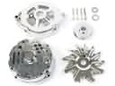 Toyota MR2 Spyder Alternator Case Kit
 Toyota MR2 Spyder Alternator Pulley
 Toyota MR2 Spyder Armature
 Toyota MR2 Spyder Battery Terminal
 Toyota MR2 Spyder Battery Tray
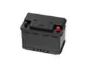 Toyota MR2 Spyder Car Battery
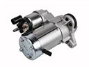 Toyota MR2 Spyder Starter
 Toyota MR2 Spyder Starter Brush
 Toyota MR2 Spyder Starter Solenoid
 Toyota MR2 Spyder Voltage Regulator