×
ToyotaParts- Hello
- Login or Register
- Quick Links
- Live Chat
- Track Order
- Parts Availability
- RMA
- Help Center
- Contact Us
- Shop for
- Toyota Parts
- Scion Parts
My Garage
My Account
Cart
OEM 2002 Toyota MR2 Spyder Alternator
Generator- Select Vehicle by Model
- Select Vehicle by VIN
Select Vehicle by Model
orMake
Model
Year
Select Vehicle by VIN
For the most accurate results, select vehicle by your VIN (Vehicle Identification Number).
1 Alternator found

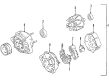
2002 Toyota MR2 Spyder Alternator
Part Number: 27060-22040-84$155.11 MSRP: $204.17You Save: $49.06 (25%)Ships in 1-3 Business DaysProduct Specifications- Other Name: Alternator Assembly, With Regulator
- Replaces: 27060-22040
- Item Weight: 12.90 Pounds
- Item Dimensions: 9.3 x 7.3 x 8.4 inches
- Condition: New
- SKU: 27060-22040-84
- Warranty: This genuine part is guaranteed by Toyota's factory warranty.
2002 Toyota MR2 Spyder Alternator
Looking for affordable OEM 2002 Toyota MR2 Spyder Alternator? Explore our comprehensive catalogue of genuine 2002 Toyota MR2 Spyder Alternator. All our parts are covered by the manufacturer's warranty. Plus, our straightforward return policy and speedy delivery service ensure an unparalleled shopping experience. We look forward to your visit!
2002 Toyota MR2 Spyder Alternator Parts Q&A
- Q: How to service the alternator on 2002 Toyota MR2 Spyder?A: You must start alternator servicing by working on the drive belt according to these steps: rotate the tensioner clockwise until the belt becomes loose enough to remove it and afterward place the tensioner correctly. The next step requires the removal of RH engine mounting insulator from the system. Begin removal of generators by first unfastening the wire clamp from its wire clip fixture on rectifier end frame components before unfastening the generator wire by removing the cap and nut. The last step includes disconnecting the generator connector. Remove the generator by taking out its two securing bolts. First for installation secure the generator to the two bolts with careful torque adjustments of 25 N.m (255 kgf.cm, 18 ft.lbf) for 12 mm heads while using 54 N.m (550 kgf.cm, 40 ft.lbf) for 14 mm head preservation. Reconnect the wire clamp to the wire clip first while you also connect the generator connector and generator wire before using the nut and cap for final wire security. Reinstall the RH engine mounting insulator followed by the drive belt installation process that must end with a clockwise turn of the drive belt tensioner to achieve proper security.
Related 2002 Toyota MR2 Spyder Parts
 2002 Toyota MR2 Spyder Alternator Bearing
 2002 Toyota MR2 Spyder Alternator Brush
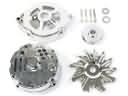 2002 Toyota MR2 Spyder Alternator Case Kit
 2002 Toyota MR2 Spyder Alternator Pulley
 2002 Toyota MR2 Spyder Armature
 2002 Toyota MR2 Spyder Battery Terminal
 2002 Toyota MR2 Spyder Battery Tray
 2002 Toyota MR2 Spyder Car Batteries
 2002 Toyota MR2 Spyder Starter Brush
 2002 Toyota MR2 Spyder Starter Drive Gear
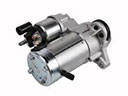 2002 Toyota MR2 Spyder Starter Motor
 2002 Toyota MR2 Spyder Voltage Regulator