×
ToyotaParts- Hello
- Login or Register
- Quick Links
- Live Chat
- Track Order
- Parts Availability
- RMA
- Help Center
- Contact Us
- Shop for
- Toyota Parts
- Scion Parts
My Garage
My Account
Cart
OEM 2004 Toyota MR2 Spyder Alternator
Generator- Select Vehicle by Model
- Select Vehicle by VIN
Select Vehicle by Model
orMake
Model
Year
Select Vehicle by VIN
For the most accurate results, select vehicle by your VIN (Vehicle Identification Number).
1 Alternator found

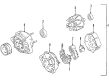
2004 Toyota MR2 Spyder Alternator
Part Number: 27060-22040-84$155.11 MSRP: $204.17You Save: $49.06 (25%)Ships in 1-3 Business DaysProduct Specifications- Other Name: Alternator Assembly, With Regulator
- Replaces: 27060-22040
- Item Weight: 12.90 Pounds
- Item Dimensions: 9.3 x 7.3 x 8.4 inches
- Condition: New
- SKU: 27060-22040-84
- Warranty: This genuine part is guaranteed by Toyota's factory warranty.
2004 Toyota MR2 Spyder Alternator
Looking for affordable OEM 2004 Toyota MR2 Spyder Alternator? Explore our comprehensive catalogue of genuine 2004 Toyota MR2 Spyder Alternator. All our parts are covered by the manufacturer's warranty. Plus, our straightforward return policy and speedy delivery service ensure an unparalleled shopping experience. We look forward to your visit!
2004 Toyota MR2 Spyder Alternator Parts Q&A
- Q: How to service and repair the alternator on 2004 Toyota MR2 Spyder?A: The first step for alternator service and repair involves multiple disassembly procedures starting with removing the rear end cover by detaching the nut and terminal insulator then proceeding to the bolt and 3 nuts and plate terminal and end cover. The service starts with removing the brush holder and voltage regulator by taking off the brush holder cover, 5 screws, brush holder, and voltage regulator followed by detaching the seal plate from the rectifier end frame. The rectifier holder needs two steps for disassembly which include taking off the 4 screws and the holder followed by removing the 4 rubber insulators. Special Service Tool 09820-63010 should be used to hold the pulley before tightening the socket clockwise to reach a torque measurement of 39 Nm (400 kgf.cm, 29 ft.lbf) while keeping the tool fastened to the rotor shaft. Fit the adapter into a vise while you place in the socket and attach the pulley nut before cautious counterclockwise nut rotation that must stop before reaching a half turn to safeguard the rotor shaft. The adapter process ends by removing both the generator and its pulley nut with pulley. Remove the rectifier end frame by uninstalling both the 4 nuts and wire clip before using Special Service Tool 09286-46011 to detach the frame and extract the generator washer from the rotor. Begin replacement with the front bearing by removing the 4 screws and bearing retainer and then push out the bearing with Special Service Tool 09950-60010 (09951-00350) and 09950-70010 (09951-07100). Press in a new bearing using the same tools followed by bearing retainer reinstallation with 4 screws at 3.0 N.m (31 kgf.cm, 27 in.lbf). Special Service Tools 09820-00021, 09820-00030 and 09285-76010 guide the process of removing the outside bearing cover followed by the bearing to prepare for placing the inside cover on the rotor before pressing in a new bearing before finishing with outside bearing cover insertion. During reassembly proceed by first inserting the rotor into the drive end frame and then laying the generator washer onto it before using a 29 mm socket wrench to press in the rectifier end frame while securing it with a wire clip and 4 nuts tightened per specified torques of 4.5 N.m (46 kgf.cm, 40 in.lbf) for Nut A and 5.4 N.m (55 kgf.cm, 48 in.lbf) for Nut B. Use hand power to tighten the pulley nut before applying Special Service Tool 09820-63010 to torque it to 39 N.m (400 kgf.cm, 29 ft.lbf) while the tool remains mounted on the pulley shaft. Before removing the generator from the tool mount Special Service Tool C into a vise then insert Special Service Tool B plus attach the pulley nut before torquing the nut to 111 N.m (1,125 kgf.cm, 81 ft.lbf). Use the 4 rubber insulators on the rectifier holder and check its direction before tightening 4 screws at 2.9 N.m (30 kgf.cm, 26 in.lbf). After placing the seal plate onto the rectifier end frame you must install the voltage regulator and brush holder using 5 screws while torqueing them to 2.0 N.m (20 kgf.cm, 18 in.lbf). Finally, cover the brush holder. Secure the rear end cover by attaching the end cover with plate terminal using a bolt followed by tightening three nuts respectively at 4.4 N.m (45 kgf.cm, 39 in.lbf) torque for nuts and 3.9 N.m (39 kgf.cm, 35 in.lbf) torque for the bolt before installing the terminal insulator with its nut tightened to 4.1 N.m (42 kgf.cm, 36 in.lbf) then check for smooth rotor movement.
Related 2004 Toyota MR2 Spyder Parts
 2004 Toyota MR2 Spyder Alternator Brush
 2004 Toyota MR2 Spyder Alternator Pulley
 2004 Toyota MR2 Spyder Armature
 2004 Toyota MR2 Spyder Battery Terminal
 2004 Toyota MR2 Spyder Battery Tray
 2004 Toyota MR2 Spyder Car Batteries
 2004 Toyota MR2 Spyder Starter Brush
 2004 Toyota MR2 Spyder Starter Drive Gear
 2004 Toyota MR2 Spyder Starter Motor
 2004 Toyota MR2 Spyder Starter Solenoid
 2004 Toyota MR2 Spyder Voltage Regulator