×
ToyotaParts- Hello
- Login or Register
- Quick Links
- Live Chat
- Track Order
- Parts Availability
- RMA
- Help Center
- Contact Us
- Shop for
- Toyota Parts
- Scion Parts
My Garage
My Account
Cart
OEM Toyota MR2 Spyder Axle Shaft
Car Axle Shaft- Select Vehicle by Model
- Select Vehicle by VIN
Select Vehicle by Model
orMake
Model
Year
Select Vehicle by VIN
For the most accurate results, select vehicle by your VIN (Vehicle Identification Number).
5 Axle Shafts found

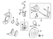
Toyota MR2 Spyder Hub, Rear Part Number: 42301-17040
$209.69 MSRP: $299.39You Save: $89.70 (30%)Ships in 1-3 Business Days
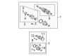
Toyota MR2 Spyder Axle Assembly, Driver Side Part Number: 42340-17151
Toyota MR2 Spyder Axle Assembly, Driver Side Part Number: 43420-17010

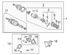
Toyota MR2 Spyder Axle Shaft
Choose genuine Axle Shaft that pass strict quality control tests. You can trust the top quality and lasting durability. Shopping for OEM Axle Shaft for your Toyota MR2 Spyder? Our website is your one-stop destination. We stock an extensive selection of genuine Toyota MR2 Spyder parts. The price is affordable so you can save more. It only takes minutes to browse and find the exact fit. Easily add to cart and check out fast. Our hassle-free return policy will keep you stress-free. We process orders quickly for swift delivery. Your parts will arrive faster, so you can get back on the road sooner.
This component is the Axle Shaft that comes with the Toyota MR2 Spyder and it is indeed a reliable and high performing part that can only be expected from Toyota. Being implemented to transmit torque from the differential to the driving wheels, the MR2 Spyder Axle Shaft allows wheels to rotate independently, thus providing grip on turn and boosting the handling in general. Made from long lasting steel material, these axle shafts are usually in a set to get the correct and full force transfer to the wheels and hence the vehicle. Specifically, the MR2 Spyder has half-shafts that are integrated with splined connections to the differential and the wheels' hub and this increases flexibility as well as easy freedom in a system such as the independent suspension system. This design not only bear the vehicle weight but also transfer the driving torque and also ensures that wheel is aligned to avoid any chance of accidents and extra fuel consumption. In the Toyota MR2 Spyder that ranged from 1999 to 2007, Axle Shaft is illustrated in the B, Standard, and S trims. It is advisable to check your MR2 Spyder Axle Shaft frequently because damages in CV joint or seals will affect the car's performance. It is for these reasons that the construction and reliability of the Toyota MR2 Spyder Axle Shaft becomes a signature in the automobile market in its capacity as a distinctive component that determines the driving experience of this famous convertible sports model. Thus the Toyota MR2 Spyder has remained a symbol of worthy ride among enthusiasts and drivers to this effect.
Toyota MR2 Spyder Axle Shaft Parts and Q&A
- Q: How to remove the axle shaft on Toyota MR2 Spyder?A:The procedure to remove an axle shaft begins with hub bearing support using Special Service Tool: 09608-16042 (09608-02021, 09608-02041) whenever vehicle weight rests upon the tool. Before separating the drive shaft from the axle hub you should take caution to prevent damage to the ABS speed sensor rotor serrations. The first maintenance step is to detach the rear wheel using 103 Nm force followed by engine under cover removal to drain the gearbox oil. To remove the drive shaft lock nut utilize Special Service Tool: 09930-00010 together with a hammer and remove the nut when braking to achieve a torque of 216 Nm (2,200 kgf-cm, 159 ft. lbs.). The technician must disconnect the flexible hose from the Shock Absorber using a torque of 29 Nm (296 kgf-cm, 21 ft. lbs.) while keeping the shock absorber bolt in place and then loosen its two lower nuts to 173 Nm (1,765 kgf-cm, 128 ft. lbs.). To disconnect the strut rod from the rear axle carrier professionals should unfasten the bolt and nut with 78 Nm (796 kgf-cm, 58 ft. lbs.) torque but must avoid rotating the nut. The removal of No. 1 lower suspension arm requires unthreaded bolt and nut tightening to 103 Nm (1,051 kgf-cm, 76 ft. lbs.). Use Special Service Tool: 09610-20012 to disconnect the No. 2 lower suspension arm after removing its nut at 49 Nm (500 kgf-cm, 36 ft. lbs.). The shock absorber maintenance requires only removal of its bottom bolt, nut, and both washers while applying engine oil to the nut threads before reinstallation. Connect the drive shaft to the axle hub using a plastic hammer while avoiding damage to the boot and ABS speed sensor rotor. Detach the two center bearing bracket bolts to remove the RH drive shaft accompanied by its center bearing assembly at 64 Nm (650 kgf-cm, 47 ft. lbs.) torque but avoid breaking the oil seal and dust cover. A brass bar and hammer should be used to extract the LH drive shaft while maintaining safety for both the oil seal and dust cover components. While installing the unit use gear oil to treat both inboard joint shaft components and differential case sliding surfaces and position the snap ring downward with its open opening facing toward the bottom while achieving 2 - 3 mm (0.08 - 0.12 inch) of axial play until the drive shaft becomes hand-unremovable. Perform inspections of the ABS speed sensor signal together with rear wheel alignment before finishing the installation procedure.
- Q: How to service and repair the axle shaft assembly on Toyota MR2 Spyder?A:The procedure to service and repair the axle shaft begins with drive shaft disassembly followed by joint play inspection of the outboard segment and outboard smooth operation and boot damage examination. The inboard joint boot clamps get removed through screwdriver use and side cutter access while sliding the inboard joint boot toward the outboard joint before marking the inboard joint shaft, tripod and outboard joint shaft for match records not using punching tools. Use a snap ring expander to remove the snap ring while placing matchmarks onto both the outboard joint shaft and tripod before extracting the tripod through use of a brass bar hit with a hammer only on the non-roll surfaces. Begin by unscrewing the inboard and outboard joint boots together with inboard joint clamps yet keeping the outboard joint intact when possible. Special Service Tool: 09950-00020 allows the inboard joint shaft dust cover removal on the LH side through pressing while the RH side requires the transaxle side dust cover and center bearing removal by putting the outside snap ring off, pressing out the bearing case, removing the straight pin followed by removing the inside snap ring with the same tool to extract the center bearing. Install new dust covers along with center bearings and straight pin and outside snap rings on the right-hand side during assembly according to the instructions provided by special service tools. A steel plate should be applied for pressing the transaxle side dust cover until it reaches the required distance. Install new temporary outboard and inboard joint boots and clamps on the shaft spline that needs protection by covering it with vinyl tape. Place the oriented tripod against the outboard joint by using matchmarked alignment and a brass bar to push it in but keep away from the roller. Add grease amounting to 140-155 grams to the outboard joint and boot before putting on the boot and subsequently apply 180-190 grams of grease to the inboard joint and its boot while aligning matchmarks for inboard joint shaft-to-outboard joint shaft installation. Secure the boot clamps on the boots using Special Service Tools 09521-24010 and 09240-00020 by adjusting the 0.8mm (0.031 inch) or less clearance value for all clamp types.


Related Toyota MR2 Spyder Parts
 Toyota MR2 Spyder Control Arm Bolt
 Toyota MR2 Spyder CV Boot
 Toyota MR2 Spyder CV Joint
 Toyota MR2 Spyder Rear Crossmember
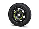 Toyota MR2 Spyder Spare Wheel
 Toyota MR2 Spyder Steering Knuckle
 Toyota MR2 Spyder Suspension Strut Rod
 Toyota MR2 Spyder Sway Bar Bracket
 Toyota MR2 Spyder Sway Bar Link
 Toyota MR2 Spyder Sway Bars
 Toyota MR2 Spyder Transfer Case Output Shaft Snap Ring
 Toyota MR2 Spyder Wheel Seal
Browse Toyota MR2 Spyder Axle Shaft by Years
2005
2004
2003
2002
2001
2000