×
ToyotaParts- Hello
- Login or Register
- Quick Links
- Live Chat
- Track Order
- Parts Availability
- RMA
- Help Center
- Contact Us
- Shop for
- Toyota Parts
- Scion Parts
My Garage
My Account
Cart
OEM 2000 Toyota MR2 Spyder Axle Shaft
Car Axle Shaft- Select Vehicle by Model
- Select Vehicle by VIN
Select Vehicle by Model
orMake
Model
Year
Select Vehicle by VIN
For the most accurate results, select vehicle by your VIN (Vehicle Identification Number).
3 Axle Shafts found

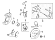
2000 Toyota MR2 Spyder Hub, Rear
Part Number: 42301-17040$207.59 MSRP: $296.40You Save: $88.81 (30%)Ships in 1-3 Business DaysProduct Specifications- Other Name: Shaft Sub-Assembly, Rear Axle; Wheel Hub, Rear; Wheel Hub Repair Kit; Shaft, Rear Axle, Passenger Side; Shaft, Rear Axle, Driver Side; Wheel Hub
- Position: Rear
- Replaces: 42301-17050
- Item Weight: 4.60 Pounds
- Item Dimensions: 6.8 x 6.8 x 6.6 inches
- Condition: New
- Fitment Type: Direct Replacement
- SKU: 42301-17040
- Warranty: This genuine part is guaranteed by Toyota's factory warranty.

 Product Specifications
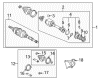
- Other Name: Shaft Assembly, Rear Drive; CV Axle Assembly, Rear Right; Axle Shaft; Shaft Assembly, Rear Drive, Passenger Side
- Position: Passenger Side
- Replaces: 42330-17190
- Part Name Code: 42330
- Item Weight: 16.20 Pounds
- Item Dimensions: 28.2 x 8.6 x 7.5 inches
- Condition: New
- Fitment Type: Direct Replacement
- SKU: 42330-17191
- Warranty: This genuine part is guaranteed by Toyota's factory warranty.

 Product Specifications
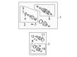
- Other Name: Shaft Assembly, Rear Drive; CV Axle Assembly, Rear Left; Axle Shaft; Shaft Assembly, Rear Drive, Driver Side
- Position: Driver Side
- Replaces: 42340-17150
- Part Name Code: 42340B
- Item Weight: 15.90 Pounds
- Item Dimensions: 28.7 x 8.3 x 7.6 inches
- Condition: New
- Fitment Type: Direct Replacement
- SKU: 42340-17151
- Warranty: This genuine part is guaranteed by Toyota's factory warranty.
2000 Toyota MR2 Spyder Axle Shaft
Looking for affordable OEM 2000 Toyota MR2 Spyder Axle Shaft? Explore our comprehensive catalogue of genuine 2000 Toyota MR2 Spyder Axle Shaft. All our parts are covered by the manufacturer's warranty. Plus, our straightforward return policy and speedy delivery service ensure an unparalleled shopping experience. We look forward to your visit!
2000 Toyota MR2 Spyder Axle Shaft Parts Q&A
- Q: How to service and repair the axle shaft on 2000 Toyota MR2 Spyder?A: Service and repair operations on axle shafts need drivers to first dismantle drive shafts then check outboard joint play and verify inboard joint sliding motion before inspecting boot damage. To detach the joint boot clamps start with a screwdriver on inboard clamps and a side cutter on outboard clamps. Move the inboard joint boot toward the outboard joint and apply marks only to the inboard joint shaft and tripod and outboard joint shaft but avoid punching the marks before removing the inboard joint shaft. A snap ring expander can remove the snap ring from the tripod after marking the outboard joint shaft and tripod. Then a brass bar assisted by a hammer removes the tripod without striking the roller. Take off the inboard and outboard joint boots and inboard joint clamps and maintain the integrity of the outboard joint. Users should remove the left-hand side dust cover of the inboard joint shaft using a press and Special Service Tool: 09950-00020 as well as use a press to remove the right-hand side transaxle side dust cover. The right-hand side center bearing removal process requires these steps: Carefully extract the outside snap ring to access the center bearing case which can be pressed out then the straight pin requires a pin punch to release it and finally the dust cover must be uninstalled using Special Service Tool: 09950-00020 before the snap rings can be separated with a snap ring expander. During reassembly, install a new dust cover on the left-hand side using a press, and for the right-hand side, install the center bearing by inserting the straight pin, using Special Service Tool: 09950-60010 (09951-00650), 09950-70010 (09951-07150) and a press to install the new center bearing, followed by the outside snap ring with a screwdriver, and the center bearing assembly to the inboard joint shaft with Special Service Tool: 09710-30021 (09710-03141) and a press, finishing with the inside snap ring using a snap ring expander and the dust cover with Special Service Tool: 09506-35010, an extension bar, and a press. A steel plate and press should be used to install the transaxle side dust cover until it reaches the target distance from the tip of the inboard joint shaft. New outboard and inboard joint boots along with clamps should be fit temporarily while vinyl tape should wrap the outboard joint shaft spline to shield it from damage. Place the tripod with the beveled side toward the outboard joint and align the matchmarks while using a brass bar and hammer for installation before installing a new snap ring. Before boot installation, pack outboard joint and boot with grease to 140-155 g while packed inboard joint and boot needs 180-190 g of grease after matchmarks alignment. Position both clamps around the boots then secure them without elongation or compression until joint cavity tightness reaches 0.8 mm (0.031 inch) or less using Special Service Tools: 09521-24010 and 09240-00020.
Related 2000 Toyota MR2 Spyder Parts
 2000 Toyota MR2 Spyder Bump Stop
 2000 Toyota MR2 Spyder CV Boot
 2000 Toyota MR2 Spyder CV Joint
 2000 Toyota MR2 Spyder Coil Spring Insulator
 2000 Toyota MR2 Spyder Coil Springs
 2000 Toyota MR2 Spyder Control Arm Bolt
 2000 Toyota MR2 Spyder Front Cross-Member
 2000 Toyota MR2 Spyder Shock And Strut Mount
 2000 Toyota MR2 Spyder Spare Wheel
 2000 Toyota MR2 Spyder Sway Bar Link
 2000 Toyota MR2 Spyder Transfer Case Output Shaft Snap Ring
 2000 Toyota MR2 Spyder Wheel Seal