×
ToyotaParts- Hello
- Login or Register
- Quick Links
- Live Chat
- Track Order
- Parts Availability
- RMA
- Help Center
- Contact Us
- Shop for
- Toyota Parts
- Scion Parts
My Garage
My Account
Cart
OEM 2003 Toyota MR2 Spyder Axle Shaft
Car Axle Shaft- Select Vehicle by Model
- Select Vehicle by VIN
Select Vehicle by Model
orMake
Model
Year
Select Vehicle by VIN
For the most accurate results, select vehicle by your VIN (Vehicle Identification Number).
3 Axle Shafts found

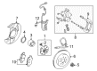
2003 Toyota MR2 Spyder Hub, Rear
Part Number: 42301-17040$207.59 MSRP: $296.40You Save: $88.81 (30%)Ships in 1-3 Business DaysProduct Specifications- Other Name: Shaft Sub-Assembly, Rear Axle; Wheel Hub, Rear; Wheel Hub Repair Kit; Shaft, Rear Axle, Passenger Side; Shaft, Rear Axle, Driver Side; Wheel Hub
- Position: Rear
- Replaces: 42301-17050
- Item Weight: 4.60 Pounds
- Item Dimensions: 6.8 x 6.8 x 6.6 inches
- Condition: New
- Fitment Type: Direct Replacement
- SKU: 42301-17040
- Warranty: This genuine part is guaranteed by Toyota's factory warranty.

 Product Specifications
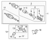
- Other Name: Shaft Assembly, Front Drive; CV Axle Assembly, Rear Right; GSP Cv Axle; Axle Shaft; Shaft Assembly, Rear Drive, Passenger Side; CV Axle Assembly
- Position: Passenger Side
- Part Name Code: 42330
- Item Weight: 16.40 Pounds
- Item Dimensions: 27.6 x 8.7 x 7.7 inches
- Condition: New
- Fitment Type: Direct Replacement
- SKU: 43410-17010
- Warranty: This genuine part is guaranteed by Toyota's factory warranty.

 Product Specifications
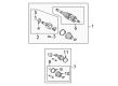
- Other Name: Shaft Assembly, Front Drive; CV Axle Assembly, Rear Left; Axle Shaft; Shaft Assembly, Rear Drive, Driver Side
- Position: Driver Side
- Part Name Code: 42340B
- Item Weight: 16.40 Pounds
- Item Dimensions: 27.4 x 8.7 x 7.7 inches
- Condition: New
- Fitment Type: Direct Replacement
- SKU: 43420-17010
- Warranty: This genuine part is guaranteed by Toyota's factory warranty.
2003 Toyota MR2 Spyder Axle Shaft
Looking for affordable OEM 2003 Toyota MR2 Spyder Axle Shaft? Explore our comprehensive catalogue of genuine 2003 Toyota MR2 Spyder Axle Shaft. All our parts are covered by the manufacturer's warranty. Plus, our straightforward return policy and speedy delivery service ensure an unparalleled shopping experience. We look forward to your visit!
2003 Toyota MR2 Spyder Axle Shaft Parts Q&A
- Q: How to remove the axle shaft assembly on 2003 Toyota MR2 Spyder?A: Start the axle shaft assembly removal process by maintaining support for the hub bearing with Special Service Tool: 09608-16042 (09608-02021, 09600-02041) whenever the vehicle weight needs to be placed on it. Attention must be paid to the ABS speed sensor rotor serrations when you separate the drive shaft from the axle hub. You should first loosen the wheel nut to a torque of 103 Nm (1,050 kgf-cm, 76 ft. lbs.) before removing the rear wheel. After that, remove the engine under covers and drain the gear oil. The drive shaft lock nut must be unstaked using Special Service Tool: 09930-00010 together with a hammer before removal while applying the brakes at 216 Nm (2,200 kgf cm, 159 ft lbs) torque. Fresh lock nut installation is required. The first step involves using a 29 Nm torque when removing the shock absorber bolt which secures the flexible hose followed by reducing lower shock absorber nuts to 173 Nm torque without unlatching the bolts. Disconnect the rear axle carrier from the strut rod by removing its bolt and nut with 78 Nm (796 kgf-cm, 58 ft. lbs.) torque but avoid turning the nut. Install the bolt after stabilizing the suspension. The No. 1 lower suspension arm bolt and nut need removal to disconnect the suspension component with a torque of 103 Nm (1,051 kgf-cm, 76 ft. lbs.). Avoid the mistake of turning the nut during installation. Apply torque to the bolt only after suspension stabilization. The No. 2 lower suspension arm requires you to first apply 49 Nm (500 kgf-cm, 36 ft. lbs.) torque to its nut before installation of a new nut followed by suspension stabilization prior to completion of the disconnect process using Special Service Tool: 09610-20012. The shock absorber maintenance requires removal of only its base bolt and nut along with two washers. Coat the thread of the nut with engine oil for installation. The drive shaft separation from the axle hub requires a plastic hammer stroke which should protect the boot and ABS speed sensor rotor from damage. When removing the RH drive shaft start by removing its two center bearing bracket bolts before gently pulling it out with the attached center bearing case by applying 64 Nm (650 kgf-cm, 47 ft. lbs.) torque but prevent any damage to the oil seal and dust cover. For the LH drive shaft, use a brass bar and hammer to remove it, again being careful not to damage the oil seal and dust cover, and during installation, apply gear oil to the inboard joint shaft and differential case sliding surfaces, ensuring the snap ring is set with its opening side facing downward, checking for contact between the inboard joint shaft and pinion shaft, and confirming 2 - 3 mm (0.08 - 0.12 inch) of axial play after installation, ensuring the drive shaft cannot be removed by hand. Check the ABS speed sensor signal as well as rear wheel alignment after completing the installation steps which follow the opposite sequence of removal.
Related 2003 Toyota MR2 Spyder Parts
 2003 Toyota MR2 Spyder Bump Stop
 2003 Toyota MR2 Spyder CV Boot
 2003 Toyota MR2 Spyder CV Joint
 2003 Toyota MR2 Spyder Coil Spring Insulator
 2003 Toyota MR2 Spyder Coil Springs
 2003 Toyota MR2 Spyder Control Arm Bolt
 2003 Toyota MR2 Spyder Front Cross-Member
 2003 Toyota MR2 Spyder Shock And Strut Mount
 2003 Toyota MR2 Spyder Spare Wheel
 2003 Toyota MR2 Spyder Sway Bar Link
 2003 Toyota MR2 Spyder Transfer Case Output Shaft Snap Ring
 2003 Toyota MR2 Spyder Wheel Seal