×
ToyotaParts- Hello
- Login or Register
- Quick Links
- Live Chat
- Track Order
- Parts Availability
- RMA
- Help Center
- Contact Us
- Shop for
- Toyota Parts
- Scion Parts
My Garage
My Account
Cart
OEM Toyota Sequoia Wheel Hub
Wheel Axle Hub- Select Vehicle by Model
- Select Vehicle by VIN
Select Vehicle by Model
orMake
Model
Year
Select Vehicle by VIN
For the most accurate results, select vehicle by your VIN (Vehicle Identification Number).
9 Wheel Hubs found


Toyota Sequoia Hub Assembly, Front Part Number: 43502-35110
$242.31 MSRP: $345.96You Save: $103.65 (30%)Ships in 1 Business Day

Toyota Sequoia Hub Assembly, Front Part Number: 43502-0C021
$223.78 MSRP: $319.52You Save: $95.74 (30%)Ships in 1-3 Business Days


Toyota Sequoia Hub Assembly, Front Part Number: 43502-35170
$224.37 MSRP: $320.34You Save: $95.97 (30%)Ships in 1-2 Business Days

Toyota Sequoia Bearing, Rear Part Number: 42450-0C020
$425.61 MSRP: $623.74You Save: $198.13 (32%)Ships in 1-2 Business Days

Toyota Sequoia Hub Assembly, Front Part Number: 43502-0C031
$223.78 MSRP: $319.52You Save: $95.74 (30%)Ships in 1-3 Business Days
Toyota Sequoia Rear Hub & Bearing, Driver Side Part Number: 42460-0C020
$344.80 MSRP: $505.32You Save: $160.52 (32%)Ships in 1-3 Business Days
Toyota Sequoia Rear Hub & Bearing, Passenger Side Part Number: 42450-0C030
$344.80 MSRP: $505.32You Save: $160.52 (32%)Ships in 1-3 Business Days
Toyota Sequoia Hub Assembly, Front Part Number: 43550-0C010
$426.64 MSRP: $625.24You Save: $198.60 (32%)Ships in 1-3 Business Days
Toyota Sequoia Hub Assembly, Front Part Number: 43550-0C020
$453.76 MSRP: $664.99You Save: $211.23 (32%)Ships in 1-3 Business Days
Toyota Sequoia Wheel Hub
Choose genuine Wheel Hub that pass strict quality control tests. You can trust the top quality and lasting durability. Shopping for OEM Wheel Hub for your Toyota Sequoia? Our website is your one-stop destination. We stock an extensive selection of genuine Toyota Sequoia parts. The price is affordable so you can save more. It only takes minutes to browse and find the exact fit. Easily add to cart and check out fast. Our hassle-free return policy will keep you stress-free. We process orders quickly for swift delivery. Your parts will arrive faster, so you can get back on the road sooner.
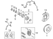
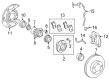
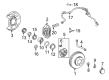
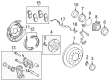
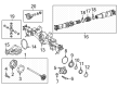
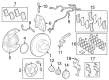
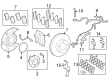
The Wheel Hub of these Toyota Sequoia cars is an indispensable part of the car that joins the wheel to the car by containing several parts such as wheel bearing, sensor, rotor, and caliper. There are many types of hub and bearing assemblies and among them the most popular is unit assembly with the sensor of the ABS. While some front-wheel-drive cars must have steering knuckle disassembly for hub unit bearing replacement, non-driven axle have hubs coming with replaceable tapered roller bearings. It is essential to pay attention to wheel bearings regular check and cleaning since bearings that are worn loose or damaged may cause noise, vibration, and most unfavorably, wheel loss. Some of the considerations to make when fitting a wheel hub entails design, fit and the price with there being low-priced OE-grade wheel hub that is accessible in the market. The Wheel Hub Assembly (WHA) in Toyota Sequoia automobiles is quite significant in enabling wheel rotation and the firm fixing of wheel to the car; installation and efficient application of torque to WHA is crucial to avert mechanical breakdowns. The use of SKF Wheel hub bearings in millions of vehicles explains the importance of WHAs in maintaining safety and reliability in vehicles' operations.
Toyota Sequoia Wheel Hub Parts and Q&A
- Q: How to service and repair the wheel hub on Toyota Sequoia?A:The front wheel and grease cap must be unwired before wheel hub servicing by using a screwdriver and hammer. To detach the Drive Shaft on 4WD models start by removing the lock cap along with the cotter pin before you unscrew the lock nut using your brakes engaged. Start by disconnecting the Speed Sensor along with the wire harness clamp from the Steering Knuckle after removing the 2 bolts. Unbolt the Brake Caliper from the steering knuckle while unlatching the brake line clamp before taking away the two bolts that fasten the brake caliper and disc unit with caution to protect the brake tube. Securely mount the brake caliper after removal. You must start by removing the Shock Absorber before disconnecting the lower Ball Joint through the removal of 4 bolts. The removal of the steering knuckle begins by removing the cotter pin before loosening the nut followed by using Special Service Tool: 09950-40011 (09951-04010, 09952-04010, 09553-04020, 09554-04010, 09955-04031, 09958-04011) to disconnect the steering knuckle before removing the nut and the knuckle while being cautious with oil seal and drive shaft boot protection. Before attaching the drive shaft into the axle hub of 2WD models use a constrained nut that must not contact the oil seal and drive shaft boot before connecting the steering knuckle to the upper suspension arm using a new cotter pin and a torque of 105 Nm (1,100 kgf-cm, 77 ft. lbs.). The lower ball joint must be attached to the steering knuckle using 4 bolts which should be torqued to 80 Nm (820 kgf-cm, 59 ft. lbs.). After that, the shock absorber needs to be installed. Place the disc and brake caliper on the vehicle with 2 bolts before torquing them to 123 Nm (1,250 kgf-cm, 90 ft. lbs.) and then fasten the brake line clamp to the steering knuckle with a bolt set to 28 Nm (285 kgf-cm, 21 ft. lbs.). Use 2 bolts to attach the steering knuckle to the speed sensor and wire harness clamp and apply torque of 8.0 Nm (82 kgf-cm, 71 ft. lbs.). The drive shaft lock nut on 4WD models requires application of brake pressure to tighten it to 235 Nm (2,400 kgf-cm, 173 ft. lbs.) while the installation of a lock cap and new cotter pin is followed by additional tightening of the nut up to 60 degrees if required. Complete the procedure by installing the grease cap followed by a front wheel installation at 110 Nm (1,150 kgf-cm, 83 ft. lbs.) while performing multiple brake depressions then checking front wheel alignment and speed sensor signals and calibrating steering angle, master cylinder pressure, yaw rate, and deceleration sensors to zero.

Related Toyota Sequoia Parts
 Toyota Sequoia Brake Pads
 Toyota Sequoia Yaw Sensor
 Toyota Sequoia Brake Caliper
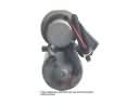 Toyota Sequoia ABS Pump And Motor Assembly
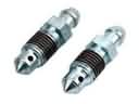 Toyota Sequoia Brake Bleeder Screw
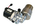 Toyota Sequoia Brake Fluid Pump
 Toyota Sequoia Hydraulic Hose
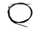 Toyota Sequoia Parking Brake Cable
 Toyota Sequoia Speed Sensor
 Toyota Sequoia Spindle Nut
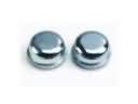 Toyota Sequoia Wheel Bearing Dust Cap
 Toyota Sequoia Wheel Stud