- Hello
- Login or Register
- Quick Links
- Live Chat
- Track Order
- Parts Availability
- RMA
- Help Center
- Contact Us
- Shop for
- Toyota Parts
- Scion Parts

Popular OEM Toyota Sequoia Parts
- Body & Hardware Parts View More >
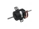
- Electrical Parts View More >
- Engine Parts View More >
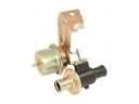
- Air & Fuel Delivery Parts View More >
- Belts & Cooling Parts View More >
- Steering Parts View More >
- Suspension Parts View More >
- Emission Control & Exhaust Parts View More >
- A/C & Heating Parts View More >
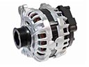
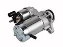
- Charging & Starting Parts View More >
- Brakes Parts View More >
- Transmission Parts View More >


Why Buy Genuine Toyota Sequoia Parts From ToyotaPartsNow.com
ToyotaPartsNow.com highlights the reliability of OEM Toyota Sequoia parts right at your fingertips. Our skilled staff assists customers in selecting the right Toyota Sequoia parts and provides expert help with any unique part requests. At ToyotaPartsNow.com, we make all Toyota Sequoia parts available to you quickly and efficiently through our fast order and reliable ship process. Our service is designed to make finding the correct Toyota Sequoia parts fast and easy whether you are an amateur or a professional. We offer access to a broad inventory that includes a wide range of Toyota years and variants. Affordable prices, quick processing and professional service are also our specialty to ensure your car remains in top condition with OEM Toyota Sequoia parts, including Headlights & Lighting. You can feel confident shopping with us because all Toyota Sequoia parts, such as Driveline & Axles you purchase from our store are of genuine quality and built to last.
The Toyota Sequoia has evolved into a full-size SUV model to meet North American customers since 2000 through three generations. The firstgen Toyota Sequoia utilized the 4.7L V8 that made 240hp 315 ft-lbs of torque and the same 4speed automatic would later swapped for a 5speed automatic in 2005. The 5.7L 3UR-FE V8 engine helped the Sequoia significantly evolve, producing 381 hp at 5600 rpm and connected to a new 6-speed automatic that resulted in improved power and fuel economy. Thanks to this, the new Sequoia gained plenty of people praises as the first truck in the Toyota lineup to receive the Ultra-Low-Emission Vehicle (ULEV) certification that's just part of Toyota's 'eco' line of guidelines. The product provides customers with a choice of rear- or four-wheel drive to suit different driving environments. The Toyota Sequoia features a convenient layout that will comfortably seat up to eight passengers, with available leather upholstery and premium audio systems. These genuine Toyota Sequoia components are constructed under precise performance standards to provide precise reliability and prolonged service life. Purolator is a manufacture OEM parts that come through authorized channels ensuring that Toyota Sequoias retain their original design and allowing owners to stay dependable on the road.
The Toyota Sequoia is a reliable vehicle with the following mechanical problems. One of the problem that can occur is the lower ball joint which can wear out prematurely due to poor finishing at the manufacturing stage. It's a problem felt in the suspension; it can also cause handling problems. Toyota has recalled their vehicles and replaced the Toyota Sequoia lower front ball joint assembly part. The other problem relates to the Toyota Sequoia oxygen sensor which may break and cause your Check Engine Light. This defects affect engine control system that may result in inefficiency in fuel consumption and over emissions. And, last but not least, the engine causes a ticking sound when the Toyota Sequoia exhaust manifold cracks. This is not only a performance issue for the engine, but it can also cause unwanted exhaust leaks. The typical remedy to this is replacing the cracked exhaust manifold. All these problems are a sign of how the Toyota Sequoia requires scheduled maintenance and prompt repairs. Proper maintenance keeps the car in a safe and operable condition. These problems can be caught early during routine check-ups and keep your Toyota Sequoia in a very reliable state.
Toyota Sequoia Parts and Q&A
- Q: How to remove the steering wheel on Toyota Sequoia?A:In order to detach the steering wheel, unplug the negative battery post first to have the SRS system put off. Then strip off steering wheel covers and pad, take off the cruise control harness and the switches. Indicate the locations and extract the steering wheel with special equipment.
- Q: How to remove the alternator on Toyota Sequoia?A:In order to discharge the alternator, you have to disconnect the negative battery terminal and wait 90 seconds. Next, loosen the engine under cover, throttle body cover and air cleaner hose. The fan and V belt must then be removed, the vane pump disconnected, and lastly the generator assembly.
- Q: How to remove the radiator on Toyota Sequoia?A:In order to take out the radiator, empty the coolant, take out the front bumper cover, and the side deflectors. Unscrew throttle body cover and air cleaner hose and set aside inlet radiator hose. In case of vehicles that have a towing system, lose the fan and shroud or otherwise leave the oil cooler assembly. Lastly, un-wire the outlet hose and strip away the radiator assembly.


