×
ToyotaParts- Hello
- Login or Register
- Quick Links
- Live Chat
- Track Order
- Parts Availability
- RMA
- Help Center
- Contact Us
- Shop for
- Toyota Parts
- Scion Parts
My Garage
My Account
Cart
OEM Toyota Sequoia Air Injection Pump
SAI Pump- Select Vehicle by Model
- Select Vehicle by VIN
Select Vehicle by Model
orMake
Model
Year
Select Vehicle by VIN
For the most accurate results, select vehicle by your VIN (Vehicle Identification Number).
4 Air Injection Pumps found


Toyota Sequoia Pump Assembly, Air, Driver Side Part Number: 17600-0F010
$491.10 MSRP: $719.72You Save: $228.62 (32%)Ships in 1-3 Business Days


Toyota Sequoia Pump Assembly, Air, Driver Side Part Number: 17610-0S010
$402.46 MSRP: $589.81You Save: $187.35 (32%)Ships in 1 Business Day


Toyota Sequoia Air Pump Part Number: 17610-0S030
$477.37 MSRP: $699.59You Save: $222.22 (32%)Ships in 1-3 Business Days


Toyota Sequoia A.I.R. Pump, Passenger Side Part Number: 17610-0C010
$440.14 MSRP: $645.03You Save: $204.89 (32%)Ships in 1-3 Business Days
Toyota Sequoia Air Injection Pump
Choose genuine Air Injection Pump that pass strict quality control tests. You can trust the top quality and lasting durability. Shopping for OEM Air Injection Pump for your Toyota Sequoia? Our website is your one-stop destination. We stock an extensive selection of genuine Toyota Sequoia parts. The price is affordable so you can save more. It only takes minutes to browse and find the exact fit. Easily add to cart and check out fast. Our hassle-free return policy will keep you stress-free. We process orders quickly for swift delivery. Your parts will arrive faster, so you can get back on the road sooner.
The Toyota Sequoia Air Injection Pump is one of the essential parts of the Toyota Sequoia models that are famed for their efficiency. This is a revolutionary element that helps in cutting the toxic emissions by injecting fresh air into the exhaust system that increases the burning of fuels. In a way that cuts HC and CO emissions, the Toyota Sequoia Air Injection Pump does not only complies with emissions standards but also decreases fuel consumption and enhances more performance. This air injection pump suits different Toyota Sequoia models and runs electric or by a belt drive depending on the engine conditions to provide proper air flow to the exhaust port and the catalyzer. Additional aspects that include one-way check valves and an air control valve help to guard the air pump from hot exhaust gases and backfires at moments when the vehicle slows down and improves safety and effectivity at the same time. The Toyota Sequoia is a reliable full-size SUV since it was launched in 2000 and the Air Injection Pump plays a major role in this. The Toyota Sequoia Air Injection Pump remains unique in this market by having improved configuration and performance, which make the Toyota Sequoia the most preferable for families who aim at being safer, environmentally friendly, and powerful on the road.
Toyota Sequoia Air Injection Pump Parts and Q&A
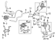
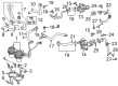
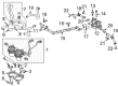
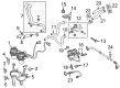
- Q: How to install the Air Injection Pump on Toyota Sequoia?A:First install the No. 1 air pump bracket before attaching the pump to its position through 3 air pump insulators and a clamp. Mount two bolts for the No. 1 air injection system hose and air pump inlet according to 8.0 Nm (82 kgf-cm, 71 in-lbf) torque specifications before ensuring that the insert hose reaches its complete stoppers position. The Bank 2 air pump assembly requires users to insert the slot onto the stud and bracket tab before tightening two nuts, a bolt, and torquing to 18 Nm for the bolt and 12 Nm for the nuts. Following the step at connect the air pump assembly connector install the No. 2 air injection system hose and secure it with 2 clamps before placing the fender apron seal using 2 clips. After installation of the front fender liner RH using 9 clips install the air pump bracket with 3 insulators and 3 collars secured by 3 bolts which need to be torqued to 10 Nm (102 kgf-cm, 7 ft-lbf). The Bank 1 air pump assembly must be fastened with 2 bolts and 2 nuts with torque set to 16 Nm (163 kgf-cm, 12 ft-lbf) and with the air pump assembly connector attached. Follow hose installation with the application of soapy water on a fresh O-ring for the water by-pass pipe sub-assembly before pushing it in using a bolt which will be torqued to 18 Nm (184 kgf-cm, 13 ft-lbf) and followed by connector clamp attachment. Perform Intake Manifold and fuel main tube and fuel return tube installation before extracting the No. 2 water by-pass pipe. Start the process by connecting the vacuum hose assembly and installing the air cleaner hose assembly before adding engine coolant for leak inspection. The procedure ends with the installation of the No. 1 engine under cover alongside the throttle body cover sub-assembly and front cowl top outer panel sub-assembly, front Wiper Motor and link assembly, cowl top ventilator louver sub-assembly, front fender to cowl side seals (RH and LH), and front wiper arm and blade assemblies (RH and LH).
- Q: How to remove the Air Injection Pump on Toyota Sequoia?A:The first step to remove the Air Injection Pump requires discharging fuel system pressure. The next step includes removing the front wiper arm and blade assembly from both right and left sides together with both front fender to cowl side seals. You must remove both the cowl top ventilator louver sub-assembly and the front Wiper Motor together with the link assembly. The first step requires eliminating both the front cowl top outer panel sub-assembly and the No. 1 engine under cover from the vehicle. Engine coolant drainage needs to occur before removing the throttle body cover sub-assembly along with the air cleaner hose assembly and vacuum hose assembly and the No. 2 water by-pass pipe. The Intake Manifold needs removal after both fuel return tube and fuel main tube disconnect. The procedure to remove the water by-pass pipe sub-assembly includes disconnecting the connector clamp before removing the bolt and pulling out the assembly to detach the O-ring. The next step involves removing the No. 1 air injection system hose by unclipping its 2 retention devices. The Bank 1 air pump assembly requires disconnecting its connector followed by removal of two bolts and two nuts. The air pump bracket can be removed after extracting all 3 bolts together with the 3 collars and 3 insulators. Ninth retainers must be removed from the front fender liner on the right side before proceeding. The installation of the No. 2 air injection system hose requires a clip remover tool to remove two clips and flipping the fender apron seal before disconnecting the air pump assembly connector and releasing two clamps and finally extracting the hose. Block out the removing process for the Bank 2 air pump assembly which consists of one bolt combined with two nuts. Finish the air pump inlet work by unbolting the 2 screws before disconnecting the No. 1 air injection system hose and No. 1 air pump bracket and removing its 3 insulators from the bracket.


Related Toyota Sequoia Parts
 Toyota Sequoia Catalytic Converter
 Toyota Sequoia Muffler
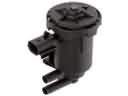 Toyota Sequoia Canister Purge Valve
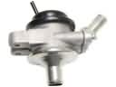 Toyota Sequoia Diverter Valve
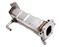 Toyota Sequoia EGR Cooler
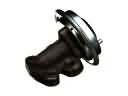 Toyota Sequoia EGR Valve
 Toyota Sequoia EGR Valve Gasket
 Toyota Sequoia Exhaust Flange Gasket
 Toyota Sequoia Exhaust Hanger
 Toyota Sequoia Exhaust Heat Shield
 Toyota Sequoia Exhaust Pipe
 Toyota Sequoia Vapor Canister