×
ToyotaParts- Hello
- Login or Register
- Quick Links
- Live Chat
- Track Order
- Parts Availability
- RMA
- Help Center
- Contact Us
- Shop for
- Toyota Parts
- Scion Parts
My Garage
My Account
Cart
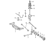
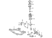
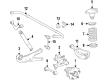
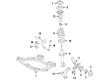
OEM Toyota Highlander Wheel Bearing
Hub Bearing- Select Vehicle by Model
- Select Vehicle by VIN
Select Vehicle by Model
orMake
Model
Year
Select Vehicle by VIN
For the most accurate results, select vehicle by your VIN (Vehicle Identification Number).
22 Wheel Bearings found


Toyota Highlander Hub Assembly, Front Part Number: 43502-0E030
$130.65 MSRP: $184.95You Save: $54.30 (30%)


Toyota Highlander Wheel Bearing Part Number: 90080-36193
$102.37 MSRP: $143.70You Save: $41.33 (29%)Ships in 1-3 Business Days

Toyota Highlander Hub & Bearing Assembly, Rear Axle, Passenger Side Part Number: 42410-0E050
$333.29 MSRP: $475.87You Save: $142.58 (30%)Ships in 1-3 Business Days

Toyota Highlander Hub Assembly, Front Part Number: 43502-28090
$129.36 MSRP: $183.12You Save: $53.76 (30%)Ships in 1-3 Business Days

Toyota Highlander Hub Assembly, Rear Part Number: 42450-0E050
$457.73 MSRP: $670.81You Save: $213.08 (32%)Ships in 1-3 Business Days

Toyota Highlander Hub & Bearing Assembly, Rear Axle, Driver Side Part Number: 42460-48011
$478.62 MSRP: $701.43You Save: $222.81 (32%)Ships in 1-2 Business Days

Toyota Highlander Hub Assembly, Front Part Number: 43502-0E010
$129.12 MSRP: $182.78You Save: $53.66 (30%)

Toyota Highlander Bearing, Passenger Side Part Number: 90363-A0007
$28.31 MSRP: $39.40You Save: $11.09 (29%)Ships in 1-3 Business Days


Toyota Highlander Wheel Bearing Part Number: 90369-A0002
$106.64 MSRP: $149.69You Save: $43.05 (29%)Ships in 1-3 Business Days


Toyota Highlander Bearing (For Front Drive Shaft) Part Number: 90080-36133
$32.13 MSRP: $44.73You Save: $12.60 (29%)Ships in 1-2 Business Days
Toyota Highlander Hub Assembly, Front Part Number: 43550-0E020
$297.53 MSRP: $424.80You Save: $127.27 (30%)Ships in 1-3 Business Days
Toyota Highlander Hub & Bearing Assembly Part Number: 42410-0E031
$286.35 MSRP: $408.83You Save: $122.48 (30%)Ships in 1-3 Business Days
Toyota Highlander Hub Assembly, Passenger Side Part Number: 42450-0E040
$575.09 MSRP: $842.81You Save: $267.72 (32%)Ships in 1-3 Business Days
Toyota Highlander Hub Assembly, Rear Part Number: 42450-0E090
$390.32 MSRP: $572.01You Save: $181.69 (32%)Ships in 1-3 Business DaysToyota Highlander Hub Assembly, Passenger Side Part Number: 42450-48011
$515.62 MSRP: $755.65You Save: $240.03 (32%)Ships in 1 Business Day
Toyota Highlander Hub&Bearing Assembly, Rear Axle Part Number: 42460-0E010
$538.66 MSRP: $789.41You Save: $250.75 (32%)Ships in 1-3 Business DaysToyota Highlander Hub&Bearing Assembly, Rear Axle Part Number: 42450-0E010
$538.66 MSRP: $789.41You Save: $250.75 (32%)Ships in 1-3 Business DaysToyota Highlander Hub Assembly, Driver Side Part Number: 42460-0E030
$575.09 MSRP: $842.81You Save: $267.72 (32%)Ships in 1-3 Business Days
Toyota Highlander Bearing(For Rear Axle Shaft Passenger Side) Part Number: 90369-38019
$157.32 MSRP: $222.71You Save: $65.39 (30%)Ships in 1-3 Business Days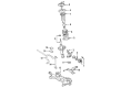
Toyota Highlander Hub Assembly, Front Part Number: 43502-02090
$183.13 MSRP: $261.46You Save: $78.33 (30%)
| Page 1 of 2 |Next >
1-20 of 22 Results
Toyota Highlander Wheel Bearing
Choose genuine Wheel Bearing that pass strict quality control tests. You can trust the top quality and lasting durability. Shopping for OEM Wheel Bearing for your Toyota Highlander? Our website is your one-stop destination. We stock an extensive selection of genuine Toyota Highlander parts. The price is affordable so you can save more. It only takes minutes to browse and find the exact fit. Easily add to cart and check out fast. Our hassle-free return policy will keep you stress-free. We process orders quickly for swift delivery. Your parts will arrive faster, so you can get back on the road sooner.
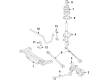
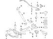
The Toyota Highlander Wheel Bearing is a critical part that significantly plays the role of boosting the Toyota Highlander's dependability as well as its performance. Mainly used to allow the wheels to rotate freely, the Wheel Bearing has the minimal friction necessary for proper working and safety. Over the years, there has been variation in the hub and bearing of the Highlander models that include integral assemblies ABS sensor, and different replaceable TR bearings. This flexibility makes it possible to fit all the five- and seven-passenger versions of the Toyota Highlander with 2WD or 4WD. Maintenance and check up on wheel bearing are important since; bearing being worn out or becoming loose may cause noise, vibration and lead to wheel detachment thus affecting efficiency and safety of the automobile. The Toyota Highlander Wheel Bearing can be described as the prime in the market especially because it is built in a way that speaks of its durability and accuracy. Also, the new generations of the Toyota Highlander feature additional technologies that are built into the hybrids in order to further increase the attractively designed machine efficiency, emphasizing the pioneers' interest in innovative solutions. As a noteworthy element in the strength and steadiness of the automobile, the Toyota Highlander Wheel Bearing has a positive impact on the general driving experience and serves as part of the car's structure that gives it the reliability associated with Toyota vehicles. From city driving to muddy paths, the Toyota Highlander Wheel Bearing is one of the critical components that contribute to the motions of this car ruthlessly.
Toyota Highlander Wheel Bearing Parts and Q&A
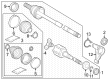
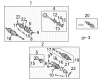
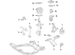
- Q: How to replace the front wheel bearing on Toyota Highlander?A:You can start front wheel bearing replacement by getting rid of the front wheel and uninstalling the front axle hub LH nut [43502H / 98-71] through Special Service Tool: 09930-00010 and striking the lock nut with a hammer while applying brake pressure. A technician first ventilates the Speed Sensor front LH [89543 / 98-170] by disassembling its bolt then untangling the sensor wire with the flexible hose from the Shock Absorber before uncoupling the sensor from the steering knuckle. Dismantle the front disc Brake Caliper assembly LH by unfastening the 2 bolts to displace it from both Drive Shafts. The front disc component [43512 / 98-71] and tie rod assembly LH [45470 / 98-76] come off through hermetic removal of the cotter pin and nut before utilizing Special Service Tool: 09628-62011 to disengage the tie rod end from the steering knuckle. The next step requires separating the front suspension arm sub-assembly lower No. 1 LH [48069 / 98-88] through bolt removal and two nut removal before extracting the front axle assembly LH with a plastic hammer until the drive shaft splits from the axle hub without endangering the boot and ABS speed sensor rotor and subsequent removal of two bolts, nuts and steering knuckle with the axle hub. Use Special Service Tool: 09628-62011 to remove the Ball Joint after both the nut and cotter pin are removed from the lower ball joint assembly front LH [43340A / 98-88]. First use a screwdriver to remove the front axle hub LH dust deflector Number 1 LH [43246B / 98-71] before using a ring plier to extract its front axle hub LH hole snap ring [43502G / 98-71]. Next apply Special Service Tool: 09520-00031 to take out the front axle hub sub-assembly LH [43502C / 98-71]. After removal of the front axle hub sub-assembly LH with Special Service Tools: 09950-00020, 09950-60010 (09951-00410), 09950- First remove the disc brake dust cover front LH [47782 / 98-83] using a torx wrench (T30) to detach its 4 bolts. The front axle hub LH bearing [43502E / 98-71] must be extracted from the steering knuckle by using Special Service Tools: 09527-17011, 09950-60010 (09951-00600), 09950-70010 (09951-07100) when the knuckle is positioned horizontally. The new front axle hub bearing [43502E / 98-71] is installed using Special Service Tools 09950-60020 (09951-00680) and 09950-70010 (09951-07100) with a press and then the disc brake dust cover front LH [47782 / 98-83] is fitted with a torx wrench (T30) and 4 bolts. Reinstall the front axle hub sub-assembly LH [43502C / 98-71] using Special Service Tool: 09608-32010, 09950-60020 (09951-00680), 09950-70010 (09951-07100) and a press, then install the front axle hub LH hole snap ring [43502G / 98-71] with a snap ring plier, followed by the front wheel bearing dust deflector No. 1 LH [43246B / 98-71] using Special Service Tool: 09316-60011 (09316-00011, 09316-00031), 09608-32010 and a hammer, ensuring the holes for the ABS speed sensor align with the steering knuckle. Secure both front lower ball joint assembly [43340A / 98-88] on the left-hand side with its nut firmly tightened to 123 Nm (1,250 kgf-cm, 90 ft. lbs.) before installing a new cotter pin with possible slight nut adjustment. Install the front axle assembly LH through its connection with the shock absorber using 2 bolts and nuts while torquing them to 210 Nm (2,143 kgf-cm, 155 ft. lbs.). Also verify that the drive shaft assembly splined section fits properly. Use 2 nuts and 1 bolt to connect the front suspension arm sub-assembly lower No. 1 LH [48069 / 98-88] at 127 Nm (1,300 kgf-cm, 94 ft. lbs.) before joining the tie rod assembly LH [45470 / 98-76] between the steering knuckle by using a new cotter pin and secure nut with a torque of 49 Nm (500 kgf-cm, 36 ft. lbs.). The process ends by checking the ABS speed sensor signal and inspecting the front wheel alignment after re-installing the front axle hub LH nut [43502H / 98-71] followed by the disc and front disc brake caliper assembly LH which requires a torque of 106.9 Nm (1,090 kgf-cm, 79 ft. lbs.) for both components.
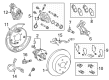
- Q: How to service and repair the rear Wheel hub and Wheel Bearing on Toyota Highlander?A:A dial indicator inspection must be conducted on the wheel hub center for looseness while the tool is set perpendicular to the measurement surface; the acceptable tolerances are 0 mm (0 in.) and any deviation requires new wheel hub assembly installation. Perform this measurement on the hub surface exterior to the bolt location where a dial indicator confirms up to 0.08 mm (0.0031 in.) runout before changing the unit. Begin by removing the front wheel before separating the right-hand side disc Brake Caliper assembly by taking out the bolt along with the flexible hose and securing the caliper while removing its two bolts. Separate the rear wheel hub and bearing assembly from the left-hand side through removal of four mounting bolts. When installing the part begin by attaching the left-hand side rear wheel hub and bearing assembly with four bolts that should be torqued to 80 N m (816 kgf cm, 59 ft. lbf). The skid control sensor wire needs to be reconnected before inspecting bearing backlash and wheel hub deviation and finally installing the rear disc. Install the two bolts on the right-hand side rear disc brake caliper assembly where torque should be set to 78 N m (800 kgf cm, 58 ft. lbf) and secure the flexible hose with a bolt torqued to 19 N m (194 kgf cm, 14 ft. lbf). For installation of the rear wheel utilize a torque of 103 N m (1,050 kgf cm, 76 ft. lbf) then inspect wheel alignment and verify the ABS speed sensor signal.


Related Toyota Highlander Parts
 Toyota Highlander Brake Pads
 Toyota Highlander Speed Sensor
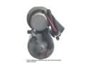 Toyota Highlander ABS Pump And Motor Assembly
 Toyota Highlander Brake Caliper Bracket
 Toyota Highlander Brake Caliper Piston
 Toyota Highlander Brake Line
 Toyota Highlander Brake Rotor
 Toyota Highlander Hydraulic Hose
 Toyota Highlander Parking Brake Cable
 Toyota Highlander Spindle Nut
 Toyota Highlander Wheel Cylinder Repair Kit
 Toyota Highlander Yaw Sensor