×
ToyotaParts- Hello
- Login or Register
- Quick Links
- Live Chat
- Track Order
- Parts Availability
- RMA
- Help Center
- Contact Us
- Shop for
- Toyota Parts
- Scion Parts
My Garage
My Account
Cart
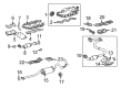
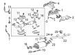
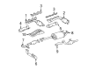
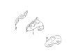
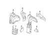
OEM Toyota Exhaust Manifold
Engine Exhaust Manifold- Select Vehicle by Model
- Select Vehicle by VIN
Select Vehicle by Model
orMake
Model
Year
Select Vehicle by VIN
For the most accurate results, select vehicle by your VIN (Vehicle Identification Number).
273 Exhaust Manifolds found


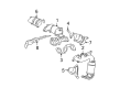
Toyota Exhaust Manifold, Driver Side Part Number: 25052-20190
$709.25 MSRP: $883.97You Save: $174.72 (20%)Ships in 1-3 Business DaysProduct Specifications- Other Name: Converter Sub-Assembly; Catalytic Converter with Integrated Exhaust Manifold, Left; Manifold Converter; Manifold; Converter Sub-Assembly, Exhaust Manifold
- Manufacturer Note: *115=TOYOTA/03-/Y
- Position: Driver Side


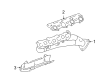
Toyota Exhaust Manifold, Passenger Side Part Number: 17140-31250
$706.41 MSRP: $1035.26You Save: $328.85 (32%)Ships in 1-3 Business DaysProduct Specifications- Other Name: Manifold Assembly, Exhaust; Catalytic Converter with Integrated Exhaust Manifold, Right; Manifold Converter; Manifold Sub-Assembly, Exhaust, Passenger Side
- Manufacturer Note: *114=*565
- Position: Passenger Side
- Replaces: 17140-31070


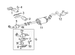
Toyota Manifold Sub-Assembly, Exhaust, Driver Side Part Number: 17105-50121
$351.16 MSRP: $514.63You Save: $163.47 (32%)Ships in 1-3 Business DaysProduct Specifications- Other Name: Manifold Sub-Assembly, Exhaust; Exhaust Manifold
- Position: Driver Side
- Replaces: 17105-50120


Toyota Manifold Sub-Assembly, Exhaust, Passenger Side Part Number: 17104-50121
$367.27 MSRP: $538.25You Save: $170.98 (32%)Ships in 1-3 Business DaysProduct Specifications- Other Name: Manifold Sub-Assembly, Exhaust; Exhaust Manifold
- Position: Passenger Side
- Replaces: 17104-50120


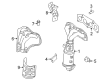
Toyota Exhaust Manifold, Driver Side Part Number: 17150-31250
$650.57 MSRP: $953.42You Save: $302.85 (32%)Ships in 1-3 Business DaysProduct Specifications- Other Name: Manifold Assembly, Exhaust; Catalytic Converter with Integrated Exhaust Manifold, Left; Manifold Converter; Manifold Sub-Assembly, Exhaust, Driver Side
- Manufacturer Note: *114=*566
- Position: Driver Side
- Replaces: 17150-31070


Toyota Manifold, Exhaust, Driver Side Part Number: 17150-50050
$737.06 MSRP: $1080.17You Save: $343.11 (32%)Ships in 1-2 Business DaysProduct Specifications- Other Name: Manifold Assembly, Exhaust; Exhaust Manifold
- Position: Driver Side


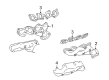
Toyota Exhaust Manifold, Driver Side Part Number: 17150-0P100
$750.45 MSRP: $1099.79You Save: $349.34 (32%)Product Specifications- Other Name: Manifold Assembly, Exhaust; Catalytic Converter with Integrated Exhaust Manifold, Left; Manifold Converter; Manifold Sub-Assembly, Exhaust, Driver Side
- Position: Driver Side
- Replaces: 17150-0P070, 17150-0P010

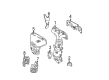
Toyota Exhaust Manifold, Passenger Side Part Number: 17140-0P100
$750.45 MSRP: $1099.79You Save: $349.34 (32%)Ships in 1-3 Business DaysProduct Specifications- Other Name: Manifold Assembly, Exhaust; Catalytic Converter with Integrated Exhaust Manifold, Right; Manifold Converter; Manifold Sub-Assembly, Exhaust, Passenger Side
- Position: Passenger Side
- Replaces: 17140-0P070


Toyota Exhaust Manifold Part Number: 17141-75130
$268.87 MSRP: $383.89You Save: $115.02 (30%)Ships in 1-3 Business DaysProduct Specifications- Other Name: Manifold, Exhaust; Catalytic Converter


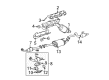
Toyota Exhaust Manifold, Passenger Side Part Number: 25051-20040
$764.75 MSRP: $953.14You Save: $188.39 (20%)Ships in 1-3 Business DaysProduct Specifications- Other Name: Converter Sub-Assembly; Catalytic Converter with Integrated Exhaust Manifold, Right; Manifold Converter; Manifold; Converter Sub-Assembly, Exhaust Manifold
- Manufacturer Note: *115=TOYOTA/03-/Y
- Position: Passenger Side


Toyota Manifold Sub-Assembly, Exhaust, Driver Side Part Number: 17105-50170
$581.90 MSRP: $852.79You Save: $270.89 (32%)Ships in 1-2 Business DaysProduct Specifications- Other Name: Manifold Sub-Assembly, Exhaust; Exhaust Manifold
- Position: Driver Side


Toyota Manifold Sub-Assembly, Exhaust, Passenger Side Part Number: 17104-50180
$652.50 MSRP: $956.25You Save: $303.75 (32%)Ships in 1-3 Business DaysProduct Specifications- Other Name: Manifold Sub-Assembly, Exhaust; Exhaust Manifold
- Position: Passenger Side

Toyota Manifold Sub-Assembly, Exhaust, Passenger Side Part Number: 17140-50060
$797.55 MSRP: $1168.82You Save: $371.27 (32%)Ships in 1 Business DayProduct Specifications- Other Name: Manifold Assembly, Exhaust; Exhaust Manifold
- Position: Passenger Side


Toyota Exhaust Manifold, Driver Side Part Number: 25052-20110
$365.57 MSRP: $455.63You Save: $90.06 (20%)Ships in 1-3 Business DaysProduct Specifications- Other Name: Converter Sub-Assembly; Catalytic Converter with Integrated Exhaust Manifold, Left; Manifold Converter; Converter Sub-Assembly, Exhaust Manifold
- Manufacturer Note: MARK 20110
- Position: Driver Side
- Replaces: 25052-20100


Toyota Exhaust Manifold Part Number: 25051-0H050
$692.23 MSRP: $862.75You Save: $170.52 (20%)Product Specifications- Other Name: Converter Sub-Assembly; Catalytic Converter with Integrated Exhaust Manifold; Manifold Converter; Converter Sub-Assembly, Exhaust Manifold
- Manufacturer Note: *108
- Replaces: 25051-28330


Toyota Exhaust Manifold, Passenger Side Part Number: 17104-50220
$342.96 MSRP: $489.68You Save: $146.72 (30%)Ships in 1-3 Business DaysProduct Specifications- Other Name: Manifold Sub-Assembly, Exhaust; Exhaust Manifold, Right; Manifold Sub-Assembly, Exhaust, Passenger Side
- Position: Passenger Side


Toyota Exhaust Manifold Part Number: 25051-28340
$703.12 MSRP: $876.33You Save: $173.21 (20%)Ships in 1 Business DayProduct Specifications- Other Name: Converter Sub-Assembly; Catalytic Converter with Integrated Exhaust Manifold; Manifold Converter; Converter Sub-Assembly, Exhaust Manifold
- Replaces: 25051-28360


Toyota Exhaust Manifold Part Number: 25051-0H040
$845.68 MSRP: $1054.01You Save: $208.33 (20%)Product Specifications- Other Name: Converter Sub-Assembly; Catalytic Converter with Integrated Exhaust Manifold; Manifold Converter; Manifold; Converter Sub-Assembly, Exhaust Manifold

Toyota Exhaust Manifold, Driver Side Part Number: 17150-0P230
$547.40 MSRP: $802.22You Save: $254.82 (32%)Ships in 1-2 Business DaysProduct Specifications- Other Name: Manifold Assembly, Exhaust; Catalytic Converter with Integrated Exhaust Manifold, Left; Manifold Sub-Assembly, Exhaust, Driver Side
- Position: Driver Side

Toyota Exhaust Manifold, Passenger Side Part Number: 17140-0P140
$894.14 MSRP: $1310.38You Save: $416.24 (32%)Product Specifications- Other Name: Manifold Assembly, Exhaust; Catalytic Converter with Integrated Exhaust Manifold, Right; Manifold Converter; Manifold Sub-Assembly, Exhaust, Passenger Side
- Manufacturer Note: MEXICO SPEC
- Position: Passenger Side
| Page 1 of 14 |Next >
1-20 of 273 Results
Toyota Exhaust Manifold
OEM parts deliver unmatched quality you can rely on. They pass extensive quality control inspections. Toyota produces them to the official factory specifications. This process helps prevent defects and imperfections. So you can get exceptional lifespan and a flawless fit. Need new OEM Toyota Exhaust Manifold? You'll love our wide selection of genuine options. Shop in minutes and skip the hunt. Our prices are unbeatable, you'll save time and money. It's easy to shop and find the right piece. Our committed customer service team gives professional help from start to finish. Every part includes a manufacturer's warranty. We ship quickly, your parts will arrive fast at your door.
Toyota Exhaust Manifold rapidly evacuates engine exhaust to avoid effects of power output and air quality in the cabin. Toyota grew a startup company in 1937 in Japan to an international symbol through eliminating waste and empowering factory floors. Toyota maintains the momentum through TNGA which makes the body rigid, sharpens handling, enhances safety and reduces the cost of production to ordinary drivers across the world. In 2022, Toyota expanded hybrid choices, optimizing Hybrid Synergy Drive and sprinkling batteries on sedans, SUVs, pickups and even light commercial rigs, cutting fuel stops. Drivers in Toyota also extend a RAV4 plug-in to 42 electric miles and it has been verified that it is also economical and does not compromise on fast acceleration and all-weather traction. The Exhaust Manifold connects to the cylinder head, collects hot gases which are then accelerated to the catalytic converter before pressure can bounce back preventing heat soak and droning noise. Both thick cast iron and thin stainless headers are available in Exhaust Manifold shape, which determines the speed of flow, engine power, and the more the feel of the inside, the better the getaway feeling. Wraps or ceramic coats reduce under-hood temperatures but overload the Exhaust Manifold with time and thus smart airflow becomes more important. Removing tuned Exhaust Manifold and replacing it with a smoother runner to increase horsepower does not require manipulation of fuel maps.
Toyota Exhaust Manifold Parts and Q&A
- Q: How to remove and reinstall exhaust manifolds in V6 engine on 1995 through 2004 Toyota Tacoma?A:Disconnect the negative cable from the battery, ensuring you have the correct activation code for the stereo if it has an anti-theft system. Spray penetrating oil on the exhaust manifold fasteners and allow it to soak in. Remove the exhaust crossover pipe from the back of the cylinder heads. Take off the EGR pipe from the exhaust manifold. Unbolt the exhaust manifolds from the cylinder heads and carefully inspect the manifolds and fasteners for cracks and damage. Use a scraper to eliminate all traces of old gasket material and carbon deposits from the mating surfaces of the manifolds and cylinder heads. If there was a gasket leak, have the manifolds checked for warpage at an automotive machine shop and resurfaced if necessary. Position new gaskets over the cylinder head studs, install the manifolds, and thread the mounting nuts into place. Working from the center out, tighten the nuts to the specified torque. Reinstall the remaining parts in the reverse order of removal, using new gaskets when connecting the exhaust pipes. Finally, run the engine and check for exhaust leaks.
- Q: How to remove and reinstall exhaust manifolds in V8 engine on Toyota Tundra?A:For 2UZ-FE engines, start by disconnecting the cable from the negative battery terminal, then remove the heat shields from the exhaust manifolds and disconnect the oxygen sensor wiring. Apply penetrating oil to the exhaust manifold and exhaust flange fasteners, allowing it to soak in before removing the exhaust pipe flange nuts and unbolting the exhaust manifolds from the cylinder heads. For 1UR-FE, 3UR-FE, and 3UR-FBE engines, remove the exhaust pipe flange nuts and lower the exhaust pipe, then take out the lower engine splash shield to access components underneath. Drain the engine coolant, remove the engine cover, air filter housing, drivebelt, upper and lower radiator hoses, and the fan shroud. Take off the inner fender seal and wheel housing splash shield from the side of the manifold being removed. For the right side manifold, remove the engine oil dipstick tube, power steering pump, alternator, heat shield fasteners, and the exhaust manifold nuts along with the manifold and gaskets. For the left side manifold, remove the A/C compressor and place it aside, then for 4WD models, remove the front driveshaft and its heat shield. Make aligning marks and disconnect the steering coupler, followed by removing the heat shield fasteners and the exhaust manifold nuts. Inspect all manifolds and fasteners for cracks and damage, then use a scraper to eliminate old gasket material and carbon deposits from the mating surfaces. Check for warpage if the gasket was leaking, and resurface if necessary. Position new gaskets over the cylinder head studs, install the manifolds, and thread the mounting nuts into place. Tighten the nuts to the specified torque in three or four equal steps, then reinstall the remaining parts in reverse order, using new gaskets for the exhaust pipes. Finally, run the engine and check for exhaust leaks.


Related Toyota Parts
 Toyota Catalytic Converter
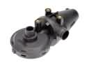 Toyota PCV Valve
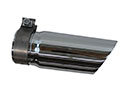 Toyota Exhaust Tip
 Toyota Muffler
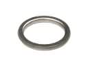 Toyota Exhaust Flange Gasket
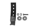 Toyota Exhaust Hanger
 Toyota Exhaust Heat Shield
 Toyota Exhaust Manifold Gasket
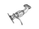 Toyota Exhaust Pipe
 Toyota Vapor Pressure Sensor
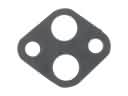 Toyota EGR Valve Gasket
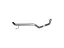 Toyota Tail Pipe
Browse Toyota Exhaust Manifold by Models
Tacoma 4Runner Camry Tundra Corolla RAV4 Highlander Prius Sienna Land Cruiser Pickup FJ Cruiser 86 Sequoia T100 Avalon Celica Supra Yaris Matrix MR2 Solara Venza GR86 Echo C-HR Cressida Grand Highlander Paseo Previa Prius C Prius Prime Corolla Cross Corolla iM Crown Crown Signia GR Corolla MR2 Spyder Prius V Starlet Tercel Van Yaris iA Prius Plug-In Prius AWD-e RAV4 Prime