×
ToyotaParts- Hello
- Login or Register
- Quick Links
- Live Chat
- Track Order
- Parts Availability
- RMA
- Help Center
- Contact Us
- Shop for
- Toyota Parts
- Scion Parts
My Garage
My Account
Cart
OEM Toyota Land Cruiser Exhaust Manifold
Engine Exhaust Manifold- Select Vehicle by Model
- Select Vehicle by VIN
Select Vehicle by Model
orMake
Model
Year
Select Vehicle by VIN
For the most accurate results, select vehicle by your VIN (Vehicle Identification Number).
14 Exhaust Manifolds found


Toyota Land Cruiser Manifold Sub-Assembly, Exhaust, Driver Side Part Number: 17105-50121
$351.16 MSRP: $514.63You Save: $163.47 (32%)Ships in 1-3 Business Days

Toyota Land Cruiser Manifold Sub-Assembly, Exhaust, Passenger Side Part Number: 17104-50121
$367.27 MSRP: $538.25You Save: $170.98 (32%)Ships in 1-3 Business Days

Toyota Land Cruiser Exhaust Manifold, Driver Side Part Number: 17105-50200
$363.87 MSRP: $533.26You Save: $169.39 (32%)Ships in 1-3 Business Days

Toyota Land Cruiser Exhaust Manifold, Passenger Side Part Number: 17104-50200
$367.27 MSRP: $538.25You Save: $170.98 (32%)Ships in 1-2 Business Days

Toyota Land Cruiser Exhaust Manifold, Driver Side Part Number: 17150-38010
$362.73 MSRP: $531.59You Save: $168.86 (32%)Ships in 1-3 Business Days
Toyota Land Cruiser Manifold Assembly, Exhaust, Passenger Side Part Number: 17140-38010
$368.07 MSRP: $539.41You Save: $171.34 (32%)Ships in 1-3 Business Days

Toyota Land Cruiser Manifold, Exhaust Part Number: 17141-66020
$175.18 MSRP: $247.99You Save: $72.81 (30%)Ships in 1-3 Business DaysToyota Land Cruiser Exhaust Manifold, Passenger Side Part Number: 17104-50210
$342.96 MSRP: $489.68You Save: $146.72 (30%)Ships in 1-3 Business Days

Toyota Land Cruiser Case, Exhaust Manifold Part Number: 17142-66010

Toyota Land Cruiser Exhaust Manifold Part Number: 17142-66020
Toyota Land Cruiser Exhaust Manifold Part Number: 17141-66030
Toyota Land Cruiser Exhaust Manifold Part Number: 17141-61080

Toyota Land Cruiser Manifold Part Number: 17100-61084
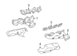
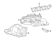
Toyota Land Cruiser Exhaust Manifold
Choose genuine Exhaust Manifold that pass strict quality control tests. You can trust the top quality and lasting durability. Shopping for OEM Exhaust Manifold for your Toyota Land Cruiser? Our website is your one-stop destination. We stock an extensive selection of genuine Toyota Land Cruiser parts. The price is affordable so you can save more. It only takes minutes to browse and find the exact fit. Easily add to cart and check out fast. Our hassle-free return policy will keep you stress-free. We process orders quickly for swift delivery. Your parts will arrive faster, so you can get back on the road sooner.
Toyota Land Cruiser Exhaust Manifold Parts and Q&A
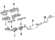
- Q: How to remove the exhaust manifold on Toyota Land Cruiser?A:The first step to remove the exhaust manifold requires removal of the front fender splash shield sub-assembly LH and RH. The technician should start by eliminating both the No. 1 engine under cover sub-assembly and the No. 2 engine under cover. A clip remover helps remove 3 clips from the front fender apron seal front RH before extracting 4 clips from the rear RH part. Use the clip remover to detach all 3 and 4 clips on the LH components of front fender apron seal and rear LH before beginning. The maintenance sequence requires the deduction of the following components: Engine oil level dipstick guide, tailpipe assembly, center Exhaust Pipe assembly, front No. 2 exhaust pipe assembly and front exhaust pipe assembly. After taking out two propeller shaft heat insulator bolts proceed with removing the two bolts from the No. 2 manifold stay. The next step involves removing 3 bolts that secure the No. 2 exhaust manifold heat insulator before removing the exhaust manifold sub-assembly LH by taking off 10 nuts, the exhaust manifold and its accompanying 2 gaskets. The technician should remove the No. 1 manifold stay using 2 bolts followed by removing the No. 1 exhaust manifold heat insulator with 3 bolts. The exhaust manifold sub-assembly RH requires removal by first removing its insulator from the exhaust manifold then the 2 nuts followed by 10 nuts and both exhaust manifold gaskets.
- Q: How to install the exhaust manifold and its associated components on Toyota Land Cruiser?A:The attachment process begins with applying new gaskets to the cylinder head and No. 2 air tube while positioning their gasket tab toward the engine front and their gasket claws toward the tube side. Secure the exhaust manifold by tightening first the 2 marked nuts (A) and 8 new nuts. After which apply an even torque to all unlabeled nuts, ultimately torque both A labeled nuts to 10 Nm (102 kgf-cm, 7 ft-lbf) for Nut A and 21 Nm (214 kgf-cm, 15 ft-lbf) for the remaining nuts. Fit the insulator to the exhaust manifold by installing two nuts which need to be tightened to 10 Nm (102 kgf-cm, 7 ft-lbf). The installation of the first No. 1 exhaust manifold heat insulator requires three bolts which need torque to reach 10 Nm (102 kgf-cm, 7 ft-lbf). The mechanics should apply 2 bolts to the No. 1 manifold stay while tightening them in sequence to reach a torque value of 40 Nm (408 kgf cm, 30 ft lbf). For the exhaust manifold sub-assembly LH reinstallation add the gasket while making sure its tab faces toward the engine back position before applying the designated nut torque schedule. The No. 2 exhaust manifold heat insulator requires installation via 3 bolts torqued to 10 Nm (102 kgf-cm, 7 ft-lbf) followed by torquing the No. 2 manifold stay with 2 bolts achieved at 40 Nm (408 kgf-cm, 30 ft-lbf). The propeller shaft heat insulator requires two bolts which should be torqued to 16 Nm (160 kgf-cm, 12 ft-lbf). Begin installing the front Exhaust Pipe assembly together with the front No. 2 exhaust pipe assembly and center exhaust pipe assembly and tailpipe assembly. The installation of the engine oil level dipstick guide must be completed before conducting a leak test on the exhaust system. Any loose components should be tightened and broken parts should be replaced if necessary. Install the front fender apron seals by attaching specified numbers of clips and add the front fender splash shield sub-assemblies LH and RH.


Related Toyota Land Cruiser Parts
 Toyota Land Cruiser Catalytic Converter
 Toyota Land Cruiser Muffler
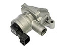 Toyota Land Cruiser Air Pump Check Valve
 Toyota Land Cruiser Canister Purge Valve
 Toyota Land Cruiser EGR Valve Gasket
 Toyota Land Cruiser Exhaust Flange Gasket
 Toyota Land Cruiser Exhaust Hanger
 Toyota Land Cruiser Exhaust Heat Shield
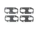 Toyota Land Cruiser Exhaust Manifold Gasket
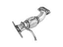 Toyota Land Cruiser Exhaust Pipe
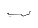 Toyota Land Cruiser Tail Pipe
 Toyota Land Cruiser Vapor Canister