×
ToyotaParts- Hello
- Login or Register
- Quick Links
- Live Chat
- Track Order
- Parts Availability
- RMA
- Help Center
- Contact Us
- Shop for
- Toyota Parts
- Scion Parts
My Garage
My Account
Cart
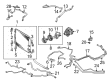
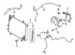
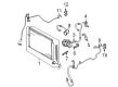
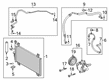
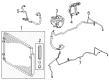
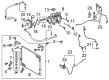
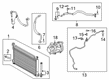
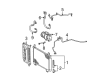
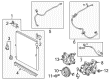
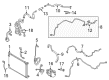
OEM Toyota A/C Compressor
Air Conditioning Compressor- Select Vehicle by Model
- Select Vehicle by VIN
Select Vehicle by Model
orMake
Model
Year
Select Vehicle by VIN
For the most accurate results, select vehicle by your VIN (Vehicle Identification Number).
207 A/C Compressors found


Toyota Reman A/C Compressor Part Number: 88320-60681-84
$385.99 MSRP: $566.79You Save: $180.80 (32%)Ships in 1-3 Business DaysProduct Specifications- Other Name: A/C Compressor
- Replaces: 88320-60680, 88320-60680-84


Toyota Compressor Assembly Part Number: 88310-0R014
$617.32 MSRP: $908.90You Save: $291.58 (33%)Ships in 1-3 Business DaysProduct Specifications- Other Name: Compressor Assembly, With Pulley; A/C Compressor; New A/C Compressor; Compressor; Compressor Assembly, W/Pulley


Toyota Compressor Part Number: 88370-47010
$551.01 MSRP: $808.72You Save: $257.71 (32%)Ships in 1-2 Business DaysProduct Specifications- Other Name: Compressor Assembly, With Pulley; A/C Compressor; Compressor Assembly, W/Motor


Toyota Compressor Part Number: 88310-WB001
$723.61 MSRP: $1060.46You Save: $336.85 (32%)Ships in 1-3 Business DaysProduct Specifications- Other Name: Compressor Assembly, With Pulley; A/C Compressor; Compressor Assembly, Cooler


Toyota Compressor Assembly, Cooler Part Number: 88320-0T010
$794.83 MSRP: $1164.83You Save: $370.00 (32%)Ships in 1-3 Business DaysProduct Specifications- Other Name: Compressor Assembly; A/C Compressor
- Replaces: 88320-0T010-84


Toyota Compressor Part Number: 88320-0C150
$504.95 MSRP: $803.93You Save: $298.98 (38%)Ships in 1-3 Business DaysProduct Specifications- Other Name: Compressor Assembly; A/C Compressor; New A/C Compressor; Compressor Assembly, Cooler


Toyota Compressor Part Number: 88310-0R040
$516.64 MSRP: $760.68You Save: $244.04 (33%)Ships in 1-3 Business DaysProduct Specifications- Other Name: Compressor Assembly, With Pulley; A/C Compressor; New A/C Compressor; Compressor Assembly, W/Pulley


Toyota Compressor Part Number: 88310-02510
$561.25 MSRP: $826.36You Save: $265.11 (33%)Ships in 1-3 Business DaysProduct Specifications- Other Name: Compressor Assembly, With Pulley; A/C Compressor; New A/C Compressor; Compressor Assembly, W/Pulley


Toyota Compressor Assembly Part Number: 88310-0T020
$585.88 MSRP: $862.63You Save: $276.75 (33%)Ships in 1-3 Business DaysProduct Specifications- Other Name: Compressor Assembly, With Pulley; A/C Compressor; New A/C Compressor; Compressor; Compressor Assembly, W/Pulley


Toyota Compressor Assembly Part Number: 88310-06390
$648.31 MSRP: $954.54You Save: $306.23 (33%)Ships in 1 Business DayProduct Specifications- Other Name: Compressor Assembly, With Pulley; A/C Compressor; New A/C Compressor; Compressor; Compressor Assembly, W/Pulley


Toyota Compressor Assembly Part Number: 88310-52750
$369.77 MSRP: $541.81You Save: $172.04 (32%)Ships in 1-3 Business DaysProduct Specifications- Other Name: Compressor Assembly, With Pulley; A/C Compressor; New A/C Compressor; Compressor; Compressor Assembly, W/Pulley


Toyota Compressor Assembly Part Number: 88320-0C160
$385.09 MSRP: $564.36You Save: $179.27 (32%)Ships in 1-2 Business DaysProduct Specifications- Other Name: A/C Compressor; New A/C Compressor; Compressor; Compressor Assembly, Cooler
- Manufacturer Note: AIR CONDITIONER-WITHOUT


Toyota Compressor Assembly Part Number: 88320-42080-84
$398.91 MSRP: $585.78You Save: $186.87 (32%)Ships in 1-3 Business DaysProduct Specifications- Other Name: Reman Compressor Assembly; A/C Compressor; Compressor


Toyota Compressor Assembly Part Number: 88310-0E141
$506.99 MSRP: $743.01You Save: $236.02 (32%)Ships in 1-3 Business DaysProduct Specifications- Other Name: Compressor Assembly, With Pulley; A/C Compressor; Compressor; Compressor Assembly, W/Pulley


Toyota Compressor Part Number: 88320-6A320
$628.10 MSRP: $920.49You Save: $292.39 (32%)Ships in 1-3 Business DaysProduct Specifications- Other Name: Compressor Assembly; A/C Compressor; New A/C Compressor; Compressor Assembly, Cooler
- Manufacturer Note: MEXICO SPEC

Toyota Compressor Assembly Part Number: 88320-08150
$719.12 MSRP: $1048.92You Save: $329.80 (32%)Ships in 1-3 Business DaysProduct Specifications- Other Name: A/C Compressor; Compressor; Compressor Assembly, Cooler
- Replaces: 88320-08070


Toyota Compressor Assembly Part Number: 88370-47092
$1080.64 MSRP: $1586.82You Save: $506.18 (32%)Ships in 1-3 Business DaysProduct Specifications- Other Name: Compressor Assembly, With Pulley; A/C Compressor; Compressor; Compressor Assembly, W/Motor
- Replaces: 88370-47090


Toyota Compressor Assembly Part Number: 88310-52481
$390.88 MSRP: $531.89You Save: $141.01 (27%)Product Specifications- Other Name: Compressor Assembly, With Pulley; A/C Compressor; New A/C Compressor; Compressor; Compressor Assembly, W/Pulley


Toyota Compressor Part Number: 88320-04070
$283.08 MSRP: $404.17You Save: $121.09 (30%)Product Specifications- Other Name: Compressor Assembly; A/C Compressor; Compressor Assembly, Cooler


Toyota Compressor Part Number: 88370-47122
$1072.40 MSRP: $1573.98You Save: $501.58 (32%)Ships in 1-3 Business DaysProduct Specifications- Other Name: Compressor Assembly, With Pulley; A/C Compressor; Compressor Assembly, W/Motor
- Replaces: 88370-47121, 88370-47120
| Page 1 of 11 |Next >
1-20 of 207 Results
Toyota A/C Compressor
OEM parts deliver unmatched quality you can rely on. They pass extensive quality control inspections. Toyota produces them to the official factory specifications. This process helps prevent defects and imperfections. So you can get exceptional lifespan and a flawless fit. Need new OEM Toyota A/C Compressor? You'll love our wide selection of genuine options. Shop in minutes and skip the hunt. Our prices are unbeatable, you'll save time and money. It's easy to shop and find the right piece. Our committed customer service team gives professional help from start to finish. Every part includes a manufacturer's warranty. We ship quickly, your parts will arrive fast at your door.
Toyota A/C Compressor forces hard in refrigerant, initiating the cooling cycle which blows cool air inside the cabin. Toyota started in 1937 and continues to prosper due to its pursuit of waste out of factories, line workers with the power to stop production during assembly once the problems are diagnosed, and lessons transformed into more efficient production. Toyota expands hybrid options on an annual basis, stocking showrooms with budget-friendly sedans, off-road crossovers, and even plug-in pick-ups, proving that efficiency can coexist with reliability without compelling buyers to adopt niche technology. Toyota is also relying on its TNGA platform to reduce weight and lower center of gravity, hone steering, and reduce crash protection while maintaining window-sticker prices at check. Toyota stuffs new Hybrid Synergy Drive units which increase electric range, punch out brisk torque, and shed range anxiety to commuters who fear fuel stops. A/C Compressor uses the low-pressure vapor and moves it to high-pressure, then directs it towards the condenser and positions a rapid heat dump to dump the hot air to cooler cabin flow. A/C Compressor is driven by engine/motor turnover and therefore constant tension on the belt prevents constant change in temperatures or accurate electric control prevents fluctuation. A/C Compressor does not change much over the years and models, having one distinct task: to ensure comfort to occupants in the hot summers. A/C Compressor maintains air inflow to condenser/evaporator coupling and ensures that every push of the dash button provides fast chill.
Toyota A/C Compressor Parts and Q&A
- Q: How should the A/C Compressor be replaced and what precautions should be taken during the process on Toyota Camry?A:The process of draining oil from the new electric inverter compressor requires the user to calculate the amount by subtracting the remaining oil from the removed electric inverter compressor from the oil capacity of 120 to 135 cc (4.1 to 4.6 fl.oz.) which exists in the new electric inverter compressor. Checking the compressor oil level properly and following safety procedures during cooler installation and removal protects against excessive oil that stops refrigerant cycle heating and triggers refrigerant malfunction. An insufficient amount of oil in the treated compressor requires leak checks and ND-OIL 11 should be used or an equivalent oil should be selected for replacing the compressor oil. The electric inverter compressor needs to be first provisionally attached with a bolt before securing with three bolts while tightening each at their specific sequence up to 25 Nm torque (255 kgf-cm 18 ft-lbf). Proceed by connecting the A connector while securing the green lock (B) beneath protected gloves followed by connector (C) attachment. When installing the No. 1 cooler refrigerant discharge hose, remove vinyl tape before applying sufficient compressor oil to both new O-ring and fitting surface. Secure the hose to the compressor with a bolt at its specified torque of 9.8 Nm (100 kgf-cm, 87 in-lbf). Reheat and complete the hose connection procedure for the No. 1 cooler refrigerant suction hose. Fasten the radiator hose outlet by adding its clip and put on your battery connections in reverse order. Engine coolant additions should be followed by leak inspection and a refrigerant charge up procedure and final tests for refrigerant leaks. Some vehicle systems need users to execute initialization after attaching the negative battery terminal connector during this process.
- Q: How to replace the A/C Compressor and its magnetic clutch in a refrigeration system on Toyota Corolla?A:The first step to replace the compressor and magnetic clutch requires exhausting refrigerant from the refrigeration system by using Special Service Tool: 07110-58060 (07117-58080, 07117-58090, 07117-78050, 07117-88060, 07117-88070, 07117-88080). The procedure for removing Cleaner cooler refrigerant suction hose No.1 requires users to remove its bolt and o-ring and cover both openings with vinyl tape to stop moisture and foreign matter from entering. The second task involves removing the discharge hose sub-assy through bolt removal and O-ring extraction and sealing the exposed ends using vinyl tape. The procedure starts by removing the engine under cover RH and fan and generator V belt then proceeding to disconnect compressor and magnetic clutch connectors while removing three bolts. You should place the compressor in a vise clamp before removing the bolt with vise pliers while taking off the hub along with the washer from the magnet clutch assembly. The snap ring expander lets you extract both the snap ring and rotor before you uninstall the connector and remover the snap ring and starter. Move on to uninstall the components of the cooler compressor. The installation process for the magnet clutch assembly starts with part matching according to the visuals followed by starter installation and utilization of a snap ring expander to put in the new snap ring with the chamfered side facing upwards. After installing the screw and connector, add the rotor together with another new snap ring that has its chamfered side facing upward and then attach the washer and hub maintaining the original magnet clutch washer arrangement. Use a 18 Nm (183 kgf.cm, 13 ft.lbf) torque value to fasten the hub by bolt. An inspection of the magnetic clutch requires a dial indicator during which you should connect the battery leads to the magnet clutch connector while measuring the clearance within 0.35 - 0.60 mm (0.013 - 0.023 in.) range. Use three maximum number of magnet clutch washers to reposition the clearance when it exists the recommended range. To replace the compressor and magnetic clutch drain the necessary oil amount by subtracting the remaining oil amount from the new unit oil capacity which equals 120 + 15 cc (4.0 + 0.5 fl.oz.). Use ND-OIL8 for compressor oil. You should torque the compressor and magnetic clutch with three bolts to 29 Nm (295 kgf.cm, 21 ft.lbf) after installation then connect the connector. The discharge hose sub-assy installation requires compressor oil application onto the new O-ring and fitting surface before torquing the bolt to 9.8 Nm (100 kgf.cm, 87 in.lbf). Rephrase and tighten the bolt connecting cooler refrigerant suction hose No.1 with 9.8 Nm (100 kgf.cm, 87 in.lbf) after applying compressor oil to its new O-ring and fitting surface. Finish the charging of refrigerant by using Special Service Tools: 07117-48130, 07117-48140, 07110-58060 (07117-58060, 07117-58070, 07117-58080, 07117-58090, 07117-78050, 07117-88060, 07117-88070, 07117-88080) and 490 plus or minus 30 g (17.28 plus or minus 1.06 oz.) of specified amount while engine heating and checking for refrigerant leaks.


Related Toyota Parts
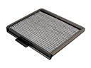 Toyota Cabin Air Filter
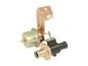 Toyota Heater Control Valve
 Toyota Ambient Temperature Sensor
 Toyota Blend Door Actuator
 Toyota Evaporator
 Toyota A/C Accumulator
 Toyota A/C Condenser
 Toyota A/C Service Cap
 Toyota A/C System Valve Core
 Toyota Blower Control Switches
 Toyota HVAC Pressure Switch
 Toyota HVAC Relay
Browse Toyota A/C Compressor by Models
Tacoma 4Runner Camry Tundra Corolla RAV4 Highlander Prius Sienna Land Cruiser Pickup FJ Cruiser 86 Sequoia T100 Avalon Celica Supra Yaris Matrix MR2 Solara Venza GR86 Echo C-HR Cressida Grand Highlander Paseo Previa Prius C Prius Prime bZ4X Corolla Cross Corolla iM Crown Crown Signia GR Corolla Mirai MR2 Spyder Prius V Starlet Tercel Van Yaris iA Prius Plug-In GR Supra Prius AWD-e RAV4 Prime