×
ToyotaParts- Hello
- Login or Register
- Quick Links
- Live Chat
- Track Order
- Parts Availability
- RMA
- Help Center
- Contact Us
- Shop for
- Toyota Parts
- Scion Parts
My Garage
My Account
Cart
OEM Toyota Cabin Air Filter
Interior Cabin Air Filter- Select Vehicle by Model
- Select Vehicle by VIN
Select Vehicle by Model
orMake
Model
Year
Select Vehicle by VIN
For the most accurate results, select vehicle by your VIN (Vehicle Identification Number).
36 Cabin Air Filters found


Toyota Air Filter Part Number: 87139-07020
$20.30 MSRP: $29.99You Save: $9.69 (33%)Product Specifications- Other Name: Element, Air Refiner; Cabin Air Filter; Filter, Interior Air; Element; Filter; Filter, Clean Air
- Replaces: 87139-52040


Toyota Air Filter Part Number: 87139-50100
$28.67 MSRP: $41.99You Save: $13.32 (32%)Ships in 1-3 Business DaysProduct Specifications- Other Name: Element, Air Refiner; Cabin Air Filter; Filter, Interior Air; Element; Filter; Filter, Clean Air
- Replaces: 87139-50060


Toyota Air Filter Part Number: 87139-0R030
$20.30 MSRP: $29.99You Save: $9.69 (33%)Product Specifications- Other Name: Element, Air Refiner; Cabin Air Filter; Filter; Filter, Clean Air
- Manufacturer Note: POLLEN FILTER,OE PART
- Replaces: 87139-28020


Toyota Filter, Clean Air Part Number: 87139-0E040
$38.23 MSRP: $52.99You Save: $14.76 (28%)Ships in 1-3 Business DaysProduct Specifications- Other Name: Element, Air Refiner; Cabin Air Filter
- Manufacturer Note: DEODORANT FILTER

Toyota Filter, Clean Air Part Number: 87139-58010
$38.23 MSRP: $52.99You Save: $14.76 (28%)Ships in 1-3 Business DaysProduct Specifications- Other Name: Element, Air Refiner; Cabin Air Filter


Toyota Air Filter Part Number: 87139-02090
$20.30 MSRP: $29.99You Save: $9.69 (33%)Ships in 1-3 Business DaysProduct Specifications- Other Name: Element, Air Refiner; Cabin Air Filter; Filter, Interior Air; Filter; Filter, Clean Air
- Replaces: 87139-0K010, 87139-0E030, 87139-52020


Toyota Cabin Air Filter Part Number: 88508-01010
$20.30 MSRP: $29.99You Save: $9.69 (33%)Ships in 1-3 Business DaysProduct Specifications- Other Name: Filer Sub-Assembly, Air; Filter Element; Filter Sub-Assembly, Clean Air
- Manufacturer Note: STANDARD

Toyota Element Part Number: 87139-07010
$20.30 MSRP: $29.99You Save: $9.69 (33%)Ships in 1-3 Business DaysProduct Specifications- Other Name: Cabin Air Filter - H; Cabin Air Filter; Filter, Interior Air; Element, Air Refiner; Filter, Clean Air


Toyota Air Filter Part Number: 87139-06030
$20.30 MSRP: $29.99You Save: $9.69 (33%)Ships in 1-3 Business DaysProduct Specifications- Other Name: Element, Air Refiner; Cabin Air Filter; Element; Filter; Filter, Clean Air
- Replaces: 87139-06040, 87139-28010, 87139-32010


Toyota Air Filter Part Number: 87139-47010-83
$20.30 MSRP: $29.99You Save: $9.69 (33%)Ships in 1-3 Business DaysProduct Specifications- Other Name: Element, Air Refiner; Cabin Air Filter; Filter, Interior Air; Filter Element; Element; Filter
- Replaces: 87139-08030, 87139-47010


Toyota Cabin Air Filter Part Number: 87139-WB001
$28.67 MSRP: $41.99You Save: $13.32 (32%)Ships in 1-3 Business DaysProduct Specifications- Other Name: Element, Air Refiner; Filter; Filter, Clean Air


Toyota Cabin Air Filter Part Number: 88568-37020
$20.30 MSRP: $29.99You Save: $9.69 (33%)Ships in 1-3 Business DaysProduct Specifications- Other Name: Filter, Air; Filter


Toyota Cabin Air Filter Part Number: 87139-F4010
$20.30 MSRP: $29.99You Save: $9.69 (33%)Ships in 1-3 Business DaysProduct Specifications- Other Name: Element, Air Refiner; Filter; Filter, Clean Air

Toyota Cabin Air Filter Part Number: 87139-33010
$28.67 MSRP: $41.99You Save: $13.32 (32%)Ships in 1-3 Business DaysProduct Specifications- Other Name: Element, Air Refiner; Filter, Interior Air; Element; Filter, Clean Air
- Manufacturer Note: DEODORANT FILTER
- Replaced by: 87139-47020


Toyota Cabin Air Filter Part Number: 88568-52010-83
$20.30 MSRP: $29.99You Save: $9.69 (33%)Ships in 1-3 Business DaysProduct Specifications- Other Name: Filter, Air A/C; Filter, Interior Air; Filter
- Replaces: 88568-52010


Toyota Cabin Air Filter Part Number: 88568-02020
$20.30 MSRP: $29.99You Save: $9.69 (33%)Ships in 1-3 Business DaysProduct Specifications- Other Name: Filter, Air; Filter; Filter, Clean Air


Toyota Air Filter Part Number: 88508-20120
$20.30 MSRP: $29.99You Save: $9.69 (33%)Ships in 1-3 Business DaysProduct Specifications- Other Name: Filter Sub-Assembly, Air; Filter, Interior Air; Cabin Air Filter; Filter Sub-Assembly, Clean Air


Toyota Air Filter Part Number: 87139-48020-83
$20.30 MSRP: $29.99You Save: $9.69 (33%)Ships in 1-2 Business DaysProduct Specifications- Other Name: Element, Air Refiner; Cabin Air Filter; Filter, Interior Air; Element; Filter
- Replaces: 87139-48020


Toyota Air Filter Part Number: 87139-0D070
$20.30 MSRP: $29.99You Save: $9.69 (33%)Ships in 1-3 Business DaysProduct Specifications- Other Name: Element, Air Refiner; Cabin Air Filter; Filter, Clean Air
- Manufacturer Note: POLLEN FILTER


Toyota Filter, Clean Air Part Number: 87139-76010
$38.23 MSRP: $52.99You Save: $14.76 (28%)Ships in 1-3 Business DaysProduct Specifications- Other Name: Element, Air Refiner; Cabin Air Filter
| Page 1 of 2 |Next >
1-20 of 36 Results
Toyota Cabin Air Filter
OEM parts deliver unmatched quality you can rely on. They pass extensive quality control inspections. Toyota produces them to the official factory specifications. This process helps prevent defects and imperfections. So you can get exceptional lifespan and a flawless fit. Need new OEM Toyota Cabin Air Filter? You'll love our wide selection of genuine options. Shop in minutes and skip the hunt. Our prices are unbeatable, you'll save time and money. It's easy to shop and find the right piece. Our committed customer service team gives professional help from start to finish. Every part includes a manufacturer's warranty. We ship quickly, your parts will arrive fast at your door.
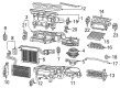
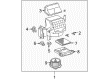
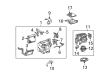
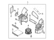
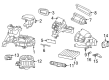
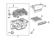
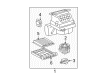
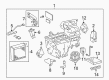
Toyota Cabin Air Filter helps to protect against road dust and fumes and allows all rides to have a cleaner breath. Toyota vehicles are produced in factories that value lean manufacturing, thus garbage is minimal, defects are repaired quicker and the customers are presented with reliable machines that hardly flinch in everyday battle. Toyota drives hybrid development, which introduces smooth electric support to sedans, crossovers, and trucks, which reduces fuel costs without decelerating acceleration or reducing cargo capacity. Toyota designed its TNGA platform to reduce the center of gravity, stiffen the chassis and make steering feel sharper so that family commuters corner with poise that even first-time drivers are surprised by. Durability is core to Toyota and the engines are known to cover long miles, the paints are known to withstand the sun and the interiors are known to remain quiet even when others are rattling, which makes value high and loyalty even higher. Cabin Air Filter is placed behind the glove box and is almost like a miniature HVAC guard, capturing dust, pollen, soot, and exhaust smells before the air is ever forced to the vents, so passengers breathe fresher air streams regardless of the traffic jam. Swapping a frequently blocked Cabin Air Filter will keep the musty vent scent out of the air, keep the heater and A/C pumping air maximally and the fan motor will not be overworked, which will save comfort and some fuel. The Cabin Air Filter can be installed and removed without the use of tools in just minutes and is one of the few jobs that can be performed almost without any sense of seriousness. Clear lungs and clear views are the result of a clean Cabin Air Filter.
Toyota Cabin Air Filter Parts and Q&A
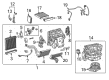
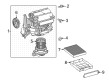
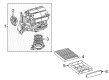
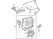
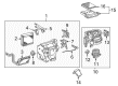
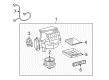
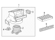
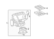
- Q: How to service and repair the cabin air filter on Toyota 4Runner?A:The maintenance process starts by removing the air filter sub-assembly through releasing its 2 claw fittings. To start the service process remove the air refiner element which is present inside the air filter cover plate.
- Q: How to install the cabin air filter and plasma cluster for TMMK made on Toyota Camry?A:The installation of both the cabin air filter and plasma cluster for TMMK made vehicles requires the operator to secure these components using 2 screws that should reach 5.4 Nm (55 kgf-cm, 48 in-lbf) of torque. Start by fastening the heater No. 1 to the register duct before adding the side nozzle duct for No. 1 defroster. Then proceed with the installation of the No. 3 instrument panel stay before moving on to the instrument panel safety pad assembly. The No. 1 defroster nozzle garnish needs to be installed after instrument panel wire assembly connection. The installation of audio components includes the front No. 2 speaker assembly (LH side) and instrument panel No. 1 speaker panel sub-assembly together with instrument panel No. 1 register assembly. The assembly list includes front pillar garnish (LH), front No. 2 speaker assembly (RH), instrument panel No. 2 speaker panel sub-assembly, and instrument panel No. 3 register assembly followed by front pillar garnish (RH). The installation sequence includes front No. 1 and No. 2 console box inserts followed by the console box assembly and console box carpet and pocket. The installer must select between the radio receiver with heater control panel assembly (w/o Navigation System) or the navigation receiver with heater control panel assembly (w/ Navigation System) according to vehicle specification. The instrument panel No. 2 register assembly joins the upper console panel sub-assembly which combine with the upper console rear panel sub-assembly and floor shift position indicator housing sub-assembly and No. 2 and No. 1 instrument cluster finish panel garnishes to finish the installation. The technical sequence involves mounting the shift lever knob sub-assembly together with lower instrument panel sub-assembly and instrument panel No. 2 under cover sub-assembly and cowl side trim sub-assembly (RH) and front door scuff plate (RH). The installation process begins with combination meter assembly while following the sequence of instrument cluster finish panel No. 1 and lower instrument panel finish panel and ending with No. 1 instrument panel sub-assembly. Implement the turn signal switch assembly by installing both its spiral cable sub-assembly and adjusting this sub-assembly. Then proceed to install the steering column cover. The last set of assembly steps includes the installation of lower instrument panel finish panel (LH), cowl side trim sub-assembly (LH), front door scuff plate (LH), steering wheel assembly, steering pad, lower No. 3 steering wheel cover and lower No. 2 steering wheel cover. Reconnect the negative terminal and check the steering pad and SRS warning system before performing system initialization because some systems need an initialization step following negative terminal reconnection.


Related Toyota Parts
 Toyota Ambient Temperature Sensor
 Toyota Blend Door Actuator
 Toyota Evaporator
 Toyota A/C Accumulator
 Toyota A/C Compressor Cut-Out Switches
 Toyota A/C Condenser
 Toyota A/C Expansion Valve
 Toyota A/C Hose
 Toyota A/C System Valve Core
 Toyota Blower Control Switches
 Toyota HVAC Pressure Switch
 Toyota HVAC Relay
Browse Toyota Cabin Air Filter by Models
Tacoma 4Runner Camry Tundra Corolla RAV4 Highlander Prius Sienna Land Cruiser FJ Cruiser 86 Sequoia Avalon Celica Yaris Matrix Solara Venza GR86 C-HR Grand Highlander Previa Prius C Prius Prime bZ4X Corolla Cross Corolla iM Crown Crown Signia GR Corolla Mirai Prius V Yaris iA Prius Plug-In GR Supra Prius AWD-e RAV4 Prime