×
ToyotaParts- Hello
- Login or Register
- Quick Links
- Live Chat
- Track Order
- Parts Availability
- RMA
- Help Center
- Contact Us
- Shop for
- Toyota Parts
- Scion Parts
My Garage
My Account
Cart
OEM Toyota Sequoia Camshaft Position Sensor
Cam Position Sensor- Select Vehicle by Model
- Select Vehicle by VIN
Select Vehicle by Model
orMake
Model
Year
Select Vehicle by VIN
For the most accurate results, select vehicle by your VIN (Vehicle Identification Number).
4 Camshaft Position Sensors found


Toyota Sequoia Camshaft Position Sensor, Driver Side Part Number: 90919-T5005
$106.16 MSRP: $149.02You Save: $42.86 (29%)Ships in 1-3 Business Days

Toyota Sequoia Sensor Assembly, Cam Position Part Number: 19300-50011
$159.79 MSRP: $226.20You Save: $66.41 (30%)Ships in 1 Business Day

Toyota Sequoia Sensor Assembly, Cam Position Part Number: 19300-50020
$166.96 MSRP: $236.35You Save: $69.39 (30%)Ships in 1-3 Business Days
Toyota Sequoia Sensor, Camshaft Position Part Number: 90919-A5007
$105.57 MSRP: $148.19You Save: $42.62 (29%)Ships in 1-3 Business Days
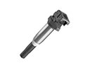
Toyota Sequoia Camshaft Position Sensor
Choose genuine Camshaft Position Sensor that pass strict quality control tests. You can trust the top quality and lasting durability. Shopping for OEM Camshaft Position Sensor for your Toyota Sequoia? Our website is your one-stop destination. We stock an extensive selection of genuine Toyota Sequoia parts. The price is affordable so you can save more. It only takes minutes to browse and find the exact fit. Easily add to cart and check out fast. Our hassle-free return policy will keep you stress-free. We process orders quickly for swift delivery. Your parts will arrive faster, so you can get back on the road sooner.
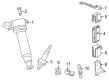
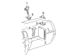
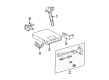
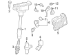
Camshaft Position Sensor in Toyota Sequoia automobiles is an important sensor that signals the position and speed of the camshaft to the engine control module in managing fuel injector and the spark timing. Usually, it is installed in the engine area, more precisely, above the camshaft, but the location can differ depending on the vehicle. Together with the crank sensor, the Camshaft Position Sensor is used to regulate engine components' operations needed for accurate fuel injection timing and accurate measurement of the engine speed. A bad Camshaft Position Sensor can result in slow performance of an automobile's engine; therefore, periodic check-up is crucial.
Toyota Sequoia Camshaft Position Sensor Parts and Q&A
- Q: How to install the camshaft position sensor and related components on Toyota Sequoia?A:Begin the camshaft position sensor installation by using 2 bolts to attach the 2 VVT sensors at 7.5 Nm (76 kgf-cm, 66 in-lbf) torque level before connecting their corresponding sensor connectors. The procedure now requires the Intake Manifold to be installed before moving onto the No. 1 fuel pipe sub-assembly and the No. 2 fuel pipe sub-assembly. The fuel pipe clamp should be installed with the No. 2 water by-pass pipe installed and then a connection of vacuum hose assembly and installation of air cleaner hose assembly. The camshaft position sensor installation must include both a bolt and stud bolt which should be tightened to 7.5 Nm (80 kgf-cm, 66 in-lbf). The installation of Drive Belt follows the complete sequence of attaching the No. 3 timing belt cover sub-assembly LH and connecting the No. 1 radiator hose. Connect the radiator hose while examining the system for fuel and coolant leaks and adding compatible engine coolant to the system. The engine shop should first install the under cover along with throttle body cover and front cowl top outer panel sub-assembly on the No. 1 engine. The installation process ends with adding the front Wiper Motor and link assembly as well as the cowl top ventilator louver sub-assembly and front fender to cowl side seals (both RH and LH components) and finally the front wiper arm and blade assemblies for RH and LH sides.
- Q: How to remove the Camshaft Position Sensor on Toyota Sequoia?A:One must start by discharging the fuel system pressure before beginning the Camshaft Position Sensor removal on a 2UZ-FE engine. The removal process begins with the No. 1 engine under cover followed by engine coolant draining before taking away the throttle body cover sub-assembly. The Drive Belt needs removal first followed by disconnection of the No. 1 radiator hose. First remove the bolting components and entire sensor from the camshaft position sensor before the sub-assembly LH timing belt cover No. 3. The technician should proceed with removing the front wiper aim and blade assembly RH and LH along with the front fender to cowl side seals RH and LH and the cowl top ventilator louver sub-assembly. Rephrase the front Wiper Motor and link assembly, front cowl top outer panel sub-assembly and air cleaner hose assembly. The first task involves disconnecting the vacuum hose assembly and extracting the No. 2 water by-pass pipe. To proceed with the task the next step must involve removing the EFI fuel pipe clamp then disconnecting the No. 2 and No. 1 fuel pipe sub-assemblies followed by removing the Intake Manifold. The conclusion of this process requires disconnecting the 2 VVT sensor connectors then removing the 2 bolts before removing the 2 VVT sensor connectors.


Related Toyota Sequoia Parts
 Toyota Sequoia Ignition Coil
 Toyota Sequoia Cooling Fan Relay
 Toyota Sequoia Daytime Running Light Relay
 Toyota Sequoia Engine Control Module
 Toyota Sequoia Headlight Relay
 Toyota Sequoia Knock Sensor
 Toyota Sequoia Neutral Safety Switch
 Toyota Sequoia Overload Relay
 Toyota Sequoia Radiator Fan Relay
 Toyota Sequoia Relay
 Toyota Sequoia Spark Plug
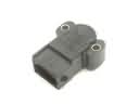 Toyota Sequoia Throttle Position Sensor