×
ToyotaParts- Hello
- Login or Register
- Quick Links
- Live Chat
- Track Order
- Parts Availability
- RMA
- Help Center
- Contact Us
- Shop for
- Toyota Parts
- Scion Parts
My Garage
My Account
Cart
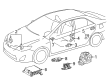
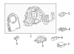
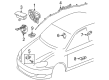
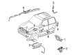
OEM Toyota Air Bag Control Module
SRS Airbag Module- Select Vehicle by Model
- Select Vehicle by VIN
Select Vehicle by Model
orMake
Model
Year
Select Vehicle by VIN
For the most accurate results, select vehicle by your VIN (Vehicle Identification Number).
457 Air Bag Control Modules found


Toyota SDM Module Part Number: 89170-0R230
$354.34 MSRP: $446.04You Save: $91.70 (21%)Ships in 1-3 Business DaysProduct Specifications- Other Name: Sensor Assembly, Air Bag; Air Bag Control Module; Diag Unit W/Sensor; Computer Assembly, Air Bag
- Replaces: 89170-42880


Toyota SDM Module Part Number: 89170-0R220
$354.34 MSRP: $446.04You Save: $91.70 (21%)Ships in 1-2 Business DaysProduct Specifications- Other Name: Sensor Assembly, Air Bag; Air Bag Control Module; Diag Unit W/Sensor; Computer Assembly, Air Bag
- Replaces: 89170-42870


Toyota SDM Module Part Number: 89170-0R191
$473.17 MSRP: $595.63You Save: $122.46 (21%)Ships in 1-3 Business DaysProduct Specifications- Other Name: Sensor Assembly, Air Bag; Air Bag Control Module; Diag Unit W/Sensor; Computer Assembly, Air Bag
- Replaces: 89170-42271


Toyota Occupant Sensor, Passenger Side Part Number: 89952-08011
$392.47 MSRP: $575.17You Save: $182.70 (32%)Ships in 1-3 Business DaysProduct Specifications- Other Name: Computer, Occupant Detection; Air Bag Seat Sensor Mat, Right; Occupant Detection Sensor; Passenger Discriminating Sensor; Occupant Module
- Position: Passenger Side
- Replaces: 89952-47020, 89952-47021


Toyota Diag Unit W/Sensor Part Number: 89170-0C640
$351.50 MSRP: $442.47You Save: $90.97 (21%)Ships in 1-3 Business DaysProduct Specifications- Other Name: Sensor Assembly, Air Bag; Air Bag Control Module; Air Bag Sensor; Center Sensor
- Manufacturer Note: MARK=AX


Toyota SDM Module Part Number: 89170-06641
$351.50 MSRP: $442.47You Save: $90.97 (21%)Ships in 1-3 Business DaysProduct Specifications- Other Name: Sensor Assembly, Air Bag; Air Bag Control Module; Diagnostic Unit; Computer Assembly, Air Bag
- Replaces: 89170-06640


Toyota SDM Module Part Number: 89170-04690
$351.50 MSRP: $442.47You Save: $90.97 (21%)Ships in 1-2 Business DaysProduct Specifications- Other Name: Sensor Assembly, Air Bag; Air Bag Control Module; Diag Unit W/Sensor; Computer Assembly, Air Bag

Toyota Diag Unit W/Sensor Part Number: 89170-0C510
$346.28 MSRP: $435.90You Save: $89.62 (21%)Ships in 1-3 Business DaysProduct Specifications- Other Name: Sensor Assembly, Air Bag; Air Bag Control Module; Air Bag Sensor; Center Sensor


Toyota Diagnostic Module Part Number: 89170-02411
$349.68 MSRP: $440.18You Save: $90.50 (21%)Ships in 1-3 Business DaysProduct Specifications- Other Name: Sensor Assembly, Air Bag; Air Bag Control Module; Diagnostic Unit
- Replaces: 89170-02410


Toyota Diagnostic Unit Part Number: 89170-35470
$362.51 MSRP: $456.33You Save: $93.82 (21%)Ships in 1-3 Business DaysProduct Specifications- Other Name: Sensor Assembly, Air Bag; Air Bag Control Module; Air Bag Sensor; Center Sensor; Computer Assembly, Air Bag
- Replaces: 89170-35400

Toyota Diag Unit W/Sensor Part Number: 89170-0C573
$369.09 MSRP: $464.61You Save: $95.52 (21%)Ships in 1-3 Business DaysProduct Specifications- Other Name: Sensor Assembly, Air Bag; Air Bag Control Module; Air Bag Sensor; Center Sensor
- Replaces: 89170-0C571, 89170-0C570, 89170-0C572


Toyota SDM Module Part Number: 89170-0E111
$364.21 MSRP: $458.47You Save: $94.26 (21%)Ships in 1-3 Business DaysProduct Specifications- Other Name: Sensor Assembly, Air Bag; Air Bag Control Module; Diag Unit W/Sensor; Computer Assembly, Air Bag
- Replaces: 89170-0E110


Toyota SDM Module Part Number: 89170-04520
$378.28 MSRP: $476.19You Save: $97.91 (21%)Ships in 1-3 Business DaysProduct Specifications- Other Name: Sensor Assembly, Air Bag; Air Bag Control Module; Diag Unit W/Sensor; Computer Assembly, Air Bag
- Replaces: 89170-04260, 89170-04261


Toyota SDM Module Part Number: 89170-35480
$394.17 MSRP: $496.19You Save: $102.02 (21%)Ships in 1-3 Business DaysProduct Specifications- Other Name: Sensor Assembly, Air Bag; Air Bag Control Module; Diag Unit W/Sensor; Computer Assembly, Air Bag


Toyota SDM Module Part Number: 89170-47601
$383.73 MSRP: $483.04You Save: $99.31 (21%)Ships in 1-3 Business DaysProduct Specifications- Other Name: Sensor Assembly, Air Bag; Air Bag Control Module; Diagnostic Unit; Computer Assembly, Air Bag
- Replaces: 89170-47600


Toyota Diag Unit W/Sensor Part Number: 89170-0C520
$384.87 MSRP: $484.47You Save: $99.60 (21%)Ships in 1-3 Business DaysProduct Specifications- Other Name: Sensor Assembly, Air Bag; Air Bag Control Module; Air Bag Sensor; Center Sensor


Toyota Diag Unit W/Sensor Part Number: 89170-0C490
$410.18 MSRP: $516.33You Save: $106.15 (21%)Ships in 1-3 Business DaysProduct Specifications- Other Name: Sensor Assembly, Air Bag; Air Bag Control Module; Computer Assembly, Air Bag
- Replaces: 89170-0C450, 89170-0C451, 89170-0C452


Toyota Diag Unit W/Sensor Part Number: 89170-0C120
$449.79 MSRP: $566.20You Save: $116.41 (21%)Ships in 1-3 Business DaysProduct Specifications- Other Name: Sensor Assembly, Air Bag; Air Bag Control Module; Air Bag Sensor; Center Sensor


Toyota Diag Unit W/Sensor Part Number: 89170-0C110
$449.79 MSRP: $566.20You Save: $116.41 (21%)Ships in 1-3 Business DaysProduct Specifications- Other Name: Sensor Assembly, Air Bag; Air Bag Control Module; Air Bag Sensor; Center Sensor

Toyota SDM Module Part Number: 89170-42280
$513.24 MSRP: $646.07You Save: $132.83 (21%)Ships in 1-3 Business DaysProduct Specifications- Other Name: Sensor Assembly, Air Bag; Air Bag Control Module; Diag Unit W/Sensor; Computer Assembly, Air Bag
| Page 1 of 23 |Next >
1-20 of 457 Results
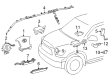
Toyota Air Bag Control Module
OEM parts deliver unmatched quality you can rely on. They pass extensive quality control inspections. Toyota produces them to the official factory specifications. This process helps prevent defects and imperfections. So you can get exceptional lifespan and a flawless fit. Need new OEM Toyota Air Bag Control Module? You'll love our wide selection of genuine options. Shop in minutes and skip the hunt. Our prices are unbeatable, you'll save time and money. It's easy to shop and find the right piece. Our committed customer service team gives professional help from start to finish. Every part includes a manufacturer's warranty. We ship quickly, your parts will arrive fast at your door.
Toyota Air Bag Control Module fires airbags fast, slashing injury risk when a hard crash hits. Toyota is supported by centuries of waste reduction manufacturing, thus the vehicles come out with fewer defects and a longer shelf life, a by-product of its insistent emphasis on identifying issues early and fixing them on the factory floor itself, keeping costs down and quality high. Toyota is retaining its drivers by matching such quality of builds with practical innovation such as Hybrid Synergy Drive, new TNGA frames which stiffen vehicles and reduce centers of gravity and plug-in arrangements which extend a tank more without compelling owners to expensive service. Toyota is also not interested in unleashing its progress with premium badges, as hatchbacks, sedans, crossovers, and pickups all have the same promise of reliability, low fuel bills, and smooth steering on the global market, so young commuters in big city traffic and families crossing the deserts experience the same promise of reliability, low bills, and smooth steering. Within the cabin of any late model, the Toyota Air Bag Control Module sampling crash sensor operates at lightning speed and undergoes self-checks each and every cycle, firing squibs as soon as the split second deceleration surpasses stored limits, protecting heads and chests even before thought has formed. The Air Bag Control Module records crash information to be reviewed later, disregarding small bumps in the parking. The continuous power-on tests allow the Air Bag Control Module to alert the drivers about wiring faults in time. The hard housing ensures the Air Bag Control Module is stable in terms of heat, dust, vibration, and daily jolts.
Toyota Air Bag Control Module Parts and Q&A
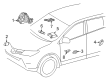
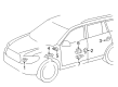
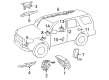
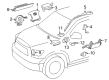
- Q: How to service the Air Bag Control Module on Toyota 4Runner?A:The service of the Air Bag Control Module requires careful reading of all Supplemental Restraint System safety precautions. Follow any necessary precautions by disconnecting the negative battery terminal cable. Starting with the console upper rear panel sub-assembly removal you must continue with the console panel sub-assembly upper procedure and subsequently remove the console upper panel garnish No. 1 and No. 2. The service requires removal of the console box assembly rear before you take off the console box mounting bracket front. Unfasten the console box duct No. 1 from the system. The procedure concludes by disassembling the 3 connectors from the center Air Bag sensor assembly before removing its 3 securing bolts.
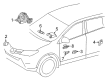
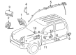
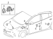
- Q: How to service the Air Bag Control Module on Toyota Camry?A:Service of the Air Bag Control Module begins with detailed study of restraint system precautions. You should disconnect the negative battery terminal cable and let it rest for 90 seconds to stop Air Bag activation before beginning work. The service begins with removing the shift lever knob sub-assembly and then proceeding to remove the No. 1 and No. 2 instrument cluster finish panel garnishes from both automatic and manual transaxle models. Remove the floor shift position indicator housing sub-assembly for automatic transaxles then continue with removal of the upper console panel and rear panel sub-assemblies for both transaxle types and the front door scuff plates and cowl side trim sub-assemblies, lower instrument panel finish panel, instrument panel No. 2 under cover sub-assembly, console box pocket, carpet, and assembly. Complete removal operations with the No. 1 and No. 2 console box inserts together with the No. 1 console box duct for automatic air conditioning system. After turning back the carpet install the center Air Bag sensor assembly by disconnecting connectors to the holder followed by removal of three bolts. Install the center Air Bag sensor assembly when the ignition is off and negative battery cable is disconnected and use three bolts torqued to 17.5 N.m (179 kgf.cm, 13 ft.lbf). Check for any damage to the assembly during the process. Check that SRS wiring remains free of pinches while inspecting all installation components for security before refitting the holder and examining the water-proof sheet. Continue by installing the No. 1 console box duct, No. 2 and No. 1 console box inserts, console box assembly, carpet, pocket, lower instrument panel sub-assembly, instrument panel No. 2 under cover sub-assembly, cowl side trim sub-assemblies, front door scuff plates, upper console panel and rear panel sub-assemblies for both transaxle types, floor shift position indicator housing sub-assembly for automatic transaxles, No. 2 and No. 1 instrument cluster finish panel garnishes, and the shift lever knob sub-assemblies for both transaxle types. The last step requires attachment of the cable to the negative battery terminal followed by checking the SRS warning light status.


Related Toyota Parts
 Toyota Key Fob
 Toyota Throttle Position Sensor
 Toyota Distributor
 Toyota Camshaft Position Sensor
 Toyota Horn
 Toyota Engine Control Module
 Toyota Headlight Relay
 Toyota Igniter
 Toyota Ignition Relay
 Toyota Neutral Safety Switch
 Toyota Transmitter
 Toyota Distributor Rotor
Browse Toyota Air Bag Control Module by Models
Tacoma 4Runner Camry Tundra Corolla RAV4 Highlander Prius Sienna Land Cruiser FJ Cruiser 86 Sequoia T100 Avalon Celica Supra Yaris Matrix MR2 Solara Venza GR86 Echo C-HR Grand Highlander Paseo Previa Prius C Prius Prime bZ4X Corolla Cross Corolla iM Crown Crown Signia GR Corolla Mirai MR2 Spyder Prius V Tercel Yaris iA Prius Plug-In GR Supra Prius AWD-e RAV4 Prime