- Hello
- Login or Register
- Quick Links
- Live Chat
- Track Order
- Parts Availability
- RMA
- Help Center
- Contact Us
- Shop for
- Toyota Parts
- Scion Parts

Popular OEM Scion xB Parts
- Body & Hardware Parts View More >
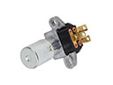
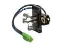
- Electrical Parts View More >
- Engine Parts View More >
- Air & Fuel Delivery Parts View More >
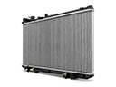
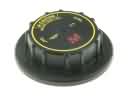
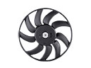
- Belts & Cooling Parts View More >
- Steering Parts View More >
- Suspension Parts View More >
- Emission Control & Exhaust Parts View More >
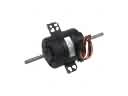
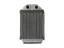
- A/C & Heating Parts View More >
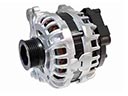
- Charging & Starting Parts View More >
- Brakes Parts View More >
- Transmission Parts View More >


Why Buy Genuine Scion xB Parts From ToyotaPartsNow.com
ToyotaPartsNow.com highlights the reliability of OEM Scion xB parts right at your fingertips. Our skilled staff assists customers in selecting the right Scion xB parts and provides expert help with any unique part requests. At ToyotaPartsNow.com, we make all Scion xB parts available to you quickly and efficiently through our fast order and reliable ship process. Our service is designed to make finding the correct Scion xB parts fast and easy whether you are an amateur or a professional. We offer access to a broad inventory that includes a wide range of Scion years and variants. Affordable prices, quick processing and professional service are also our specialty to ensure your car remains in top condition with OEM Scion xB parts. You can feel confident shopping with us because all Scion xB parts you purchase from our store are of genuine quality and built to last.
The Scion xB production spanned from June 2003 until December 2015 while delivering both practical features and strong performance. The original Scion xB model used the Toyota bB platform together with the Echo or Yaris underpinnings and received power from a 1.5-liter inline-four engine that delivered 103 horsepower and 100 lb-ft torque. The manual transmission version had five speeds while the automatic transmission version had four speeds. Its design enabled both responsive handling and superior maneuverability which made it an ideal choice for navigating through city streets. The Chicago Auto Show in 2007 marked the debut of Generation Two's Scion xB vehicle which introduced the New MC platform expanding its size to 167.3 inches length and 69.3 inches width with a height of 63.4 inches. The vehicle kept its 2.4-liter inline-four engine which now generated 158 horsepower and 162 lb-ft of torque and offered consumers the choice between a five-speed manual or a five-speed automatic transmission for better driving performance. Throughout its production period the Scion xB maintained a "Good" safety rating which showed its commitment to occupant protection. Scion xB parts made by the original manufacturer maintain factory-design specifications which protect the vehicle's performance and special attributes.
Scion xB can have a number of problems with its engine systems and climate controls. Among the frequent issues is excessive oil consumption, and in such cases, the Scion xB's low engine oil warning light might come on. This problem is usually due to infrequent oil changes, leading to sludge in the engine or worn piston rings. To remedy this, technicians normally resort to cleaning the Scion xB engine and there is often a possibility of having to remove piston rings or other internal parts. A lit check engine light is an additional cause of concern that may show there is a bad Scion xB VVT-i controller. This component retards cam timing to promote optimum power. The replacement of the VVT-i controller can resolve the warning light issue, and it is usually covered under the Scion xB's powertrain warranty. Also, the drivers might discover that their Scion xB air conditioners do not blow cold enough. This normally develops due to the need to adjust the temperature of the air using the blend door cable. The Scion xB requires proper maintenance of these systems since this is essential in terms of functionality. These problems can be avoided and prevent further complications by regular oil changes and repairs of such parts as the VVT-i controller and blend door cable.
Scion xB Parts and Q&A
- Q: How to replace the water pump on Scion xB?A:You need to replace the water pump, drain the coolant, take off engine under cover RH, fan and generator V belt. Removal of engine mounting Insulator RH and water pump pulley. Disassemble the water pump assembly, fit the new pump and gasket, and reassemble, making sure the correct torque is set. Lastly, add coolant, and leak test.
- Q: How to replace the oil filter sub-assembly safely and correctly on Scion xB?A:Wear protective clothing and gloves to prevent skin irritation with engine oil in order to change the oil filter. Empty the oil, take off the old filter with Special Service Tool: 09228-06501, wipe the top and change filter. Incorporate the right engine oil and inspect leaks. Dispose of used oil properly.
- Q: How to remove the catalytic converter on Scion xB?A:To dismantle the catalytic converter in the 2AZ-FE emission control system, you have to firstly, take away the engine under cover and the insulator of the exhaust manifold. Next, unplug air fuel ratio sensor and heated oxygen sensor. Disassemble the front exhaust pipe assembly, exhaust manifold converter sub-assembly and heat insulators.


