×
ToyotaParts- Hello
- Login or Register
- Quick Links
- Live Chat
- Track Order
- Parts Availability
- RMA
- Help Center
- Contact Us
- Shop for
- Toyota Parts
- Scion Parts
My Garage
My Account
Cart
OEM Scion xB Camshaft
Cam- Select Vehicle by Model
- Select Vehicle by VIN
Select Vehicle by Model
orMake
Model
Year
Select Vehicle by VIN
For the most accurate results, select vehicle by your VIN (Vehicle Identification Number).
4 Camshafts found


Scion xB Camshaft Part Number: 13501-21030
$257.34 MSRP: $367.42You Save: $110.08 (30%)Ships in 1-3 Business Days


Scion xB Camshaft Part Number: 13501-28060
$343.78 MSRP: $503.81You Save: $160.03 (32%)
Scion xB Camshaft Part Number: 13502-21031
$266.19 MSRP: $380.06You Save: $113.87 (30%)Ships in 1-3 Business Days
Scion xB Camshaft Part Number: 13502-28030
$323.51 MSRP: $461.90You Save: $138.39 (30%)Ships in 1-3 Business Days
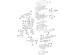
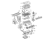
Scion xB Camshaft
Choose genuine Camshaft that pass strict quality control tests. You can trust the top quality and lasting durability. Shopping for OEM Camshaft for your Scion xB? Our website is your one-stop destination. We stock an extensive selection of genuine Scion xB parts. The price is affordable so you can save more. It only takes minutes to browse and find the exact fit. Easily add to cart and check out fast. Our hassle-free return policy will keep you stress-free. We process orders quickly for swift delivery. Your parts will arrive faster, so you can get back on the road sooner.
The scam shaft is a small but important part which helps in increasing the dependability and power of the Scion xB automobiles. Responsible for regulating the flow of gases in and out of the engine's cylinders, the Scion xB Camshaft enhances the admission of the air/fuel mixture and discharge of fumes to improve the engine's performance. Made up of particularly robust materials such as iron or steel, this camshaft is cam-operated by means of eccentric lobes that can actually control the number of rotations per minute of the engine as well as total engine power. Camshafts for different Scion xB models; OHV, SOHC, and DOHC are used and they all have their own benefits. For example, the DOHC setup has two cams for intake and exhaust; this increases its high-VIP performance, which is a plus for lovers of infinitum. The Scion xB Camshaft does not only increase the engine performance but at the same time greatly contributes to safety because a faulty camshaft has implications to the smooth running of the engine and the emission of gases. Thus, the Scion xB Camshaft is significantly important since it is suitable for nearly all of the xB models within the line. Likewise, safety is an attribute that users associate with the Scion xB with the car receiving a "Good" safety test and its camshaft is equally reliable. What sets the Scion xB Camshaft in the competitive automotive market is the superior engineering and the role it plays in the service of the car's lifespan and performance.
Scion xB Camshaft Parts and Q&A
- Q: How to install the camshaft on Scion xB?A:Initial installation demands the misalignment of key groove and straight pin on the camshaft timing gear and camshaft before turning the camshaft timing gear carefully against the camshaft until the pin finds its position in the groove without taking the camshaft to the retard angle side. Examine that the camshaft is free from the gear fringe while you tighten the flange bolt to 551 kgf-cm (54 Nm) torque (40 ft-lbf). Confirm the camshaft timing gear can reach the most retarded position while securing a lock in this angle. Before installing the bearing caps into the cylinder head, apply a light coat of engine oil to the journal part of the camshaft while aligning the paint-mark and timing mark of the camshaft timing gear. Double-check the order of front marks and numbers before continuing installation. After applying engine oil to the threads along with the bearing cap bolt heads, proceed with uniform bearing cap bolt tightening according to sequence where No. 1 bearing receives 30 Nm (301 kgf-cm, 22 ft-lbf) torque and No. 3 bearing receives 9.0 Nm (92 kgf-cm, 80 in-lbf). Place engine oil on the No. 2 camshaft journal before moving its paint mark to the camshaft timing sprocket timing mark. Secure the camshaft timing sprocket set bolt loosely and verify the front mark sequence before setting the bearing caps. Use oil on bearing cap bolt threads along with bolt heads followed by equal Bolt torque at 30 Nm (301 kgf-cm, 22 ft-lbf) on all No. 2 bearing bolts and 9.0 Nm (92 kgf-cm, 80 in-lbf) on all No. 3 bearing bolts. Use a wrench to hold the camshaft before torquing the camshaft timing sprocket set bolt to 54 Nm (551 kgf-cm, 40 ft-lbf) while checking that engine oil washers on the torques remain undamaged and the paint chain marks align with all timing marks. The No. 1 chain tensioner assembly requires users to release the ratchet pawl followed by pushing in the plunger before hooking it onto the pin. Users should install a new gasket and chain tensioner by tightening both nuts to 9.0 Nm (92 kgf-cm, 80 in-lbf). Check that the plunger extends after rotating the crankshaft clockwise and disconnect the plunger knock pin from the set hook by turning the crankshaft counterclockwise. The repair process includes alignment of the No. 1 cylinder at TDC/compression. Then check and adjust the valve clearance before installing the cylinder head cover sub-assembly by using Toyota Genuine Seal Packing Black or Three Bond 1207B or equivalent. The sub-assembly must be fastened with 8 bolts and 2 nuts combining a 11 Nm (112 kgf-cm, 8 ft-lbf) Bolt A torque and 14 Nm (143 kgf-cm, 10 ft-lbf) Bolt B torque and an 11 Nm (112 kgf-cm, 8 ft-lbf Two engine wires should be mounted with 8.4 Nm (86 kgf-cm, 74 in-lbf) torques before connecting the 2 ventilation hoses to the cylinder head cover. Before completion you must install Spark Plugs and Ignition Coils and do oil leak testing together with ignition timing checks and the removal of the No. 1 engine cover sub-assembly as well as installing the rear engine under cover RH.
- Q: How to remove the camshaft on Scion xB?A:The procedure of removing the camshaft from a 2AZ-FE engine begins with removing the rear engine under cover RH and then proceeding to take away the No. 1 engine cover sub-assembly and Ignition Coil assembly followed by the Spark Plug. After disconnecting the two ventilation hoses the technician should remove two wire harness bracket bolts before removing the eight bolts and two nuts holding the head cover and gasket. To set the No. 1 cylinder at TDC/compression position use the crankshaft pulley until you see the groove match timing mark "0" on the Timing Chain cover. Ensure the timing marks on the camshaft timing gear and sprocket show correct alignment with the No. 1 and No. 2 bearing caps; otherwise repeat the preceding manual turn of the crankshaft pulley. Use a marker to mark the chain at the position of its alignment with both timing marks. Use a wrench to hold the No. 2 camshaft before loosening the No. 2 camshaft timing gear or sprocket through the timing set bolt. Uniformly loosen and remove the specified sequence of 10 bearing cap bolts to access the No.2 camshaft and its components. Remove the 5 bearing caps and then the camshaft timing sprocket set bolt before separating the sprocket from the attached timing chain. When taking out the camshaft you must first evenly loosen and detach the 10 bearing cap bolts after that remove the 5 bearing caps and the camshaft along with camshaft timing gear when maintaining control of the timing chain. Secure the timing chain with string matter to stop it from falling inside the timing chain cover. The correct method to remove the camshaft timing gear assembly requires clamping the camshaft in a vise to stop rotation, taping all ports except the advance side port and applying 150 kPa (1.5 kgf/cm2, 22 psi) air pressure to the oil path and manually turning the gear counterclockwise. Maintain a piece of cloth to minimize oil drops while working with the paths. The procedure ends with the removal of the single flange bolt for the camshaft timing gear while keeping the 4 remaining bolts in place. Before reuse of the timing gear it is essential to free the straight pin lock.


Related Scion xB Parts
 Scion xB Valve Cover Gasket
 Scion xB Camshaft Bearing
 Scion xB Crankshaft Gear
 Scion xB Crankshaft Pulley
 Scion xB Crankshaft Seal
 Scion xB Cylinder Head Gasket
 Scion xB Dipstick Tube
 Scion xB Intake Valve
 Scion xB Oil Pump Spring
 Scion xB Rod Bearing
 Scion xB Valve Stem Seal
 Scion xB Variable Timing Sprocket