×
ToyotaParts- Hello
- Login or Register
- Quick Links
- Live Chat
- Track Order
- Parts Availability
- RMA
- Help Center
- Contact Us
- Shop for
- Toyota Parts
- Scion Parts
My Garage
My Account
Cart
OEM Toyota Pressure Plate
Clutch Pressure Plate- Select Vehicle by Model
- Select Vehicle by VIN
Select Vehicle by Model
orMake
Model
Year
Select Vehicle by VIN
For the most accurate results, select vehicle by your VIN (Vehicle Identification Number).
66 Pressure Plates found


Toyota Pressure Plate Part Number: 31210-33042
$198.85 MSRP: $283.92You Save: $85.07 (30%)Ships in 1-3 Business DaysProduct Specifications- Other Name: Cover Assembly, Clutch; Clutch Kit
- Replaces: 31210-33041, 31210-33040, 31210-28060


Toyota Pressure Plate Part Number: 31210-30261-84
$89.35 MSRP: $125.68You Save: $36.33 (29%)Ships in 1-3 Business DaysProduct Specifications- Other Name: Rean Clutch Cover; Clutch Kit; Cover Assembly
- Replaces: 31210-30261, 31210-30260

Toyota Cover Assembly, Clutch Part Number: 31210-0K281
$243.47 MSRP: $347.63You Save: $104.16 (30%)Ships in 1-3 Business DaysProduct Specifications- Replaces: 31210-0K280

Toyota Pressure Plate Part Number: 31210-14170-84
$122.69 MSRP: $174.02You Save: $51.33 (30%)Ships in 1-3 Business DaysProduct Specifications- Other Name: Reman Clutch Cover; Clutch Kit
- Replaces: 31210-14170


Toyota Pressure Plate Part Number: 31210-02190
$132.18 MSRP: $187.11You Save: $54.93 (30%)Ships in 1-3 Business DaysProduct Specifications- Other Name: Cover Assembly, Clutch; Clutch Kit


Toyota Pressure Plate Part Number: 31210-12340
$132.76 MSRP: $187.94You Save: $55.18 (30%)Ships in 1-2 Business DaysProduct Specifications- Other Name: Cover Assembly, Clutch; Clutch Kit


Toyota Pressure Plate Part Number: 31210-12291
$145.34 MSRP: $205.74You Save: $60.40 (30%)Ships in 1-3 Business DaysProduct Specifications- Other Name: Cover Assembly, Clutch; Clutch Kit
- Replaces: 31210-20380, 31210-12250, 31210-20360, 31210-12251, 31210-12290

Toyota Pressure Plate Part Number: 31210-02300
$145.34 MSRP: $205.74You Save: $60.40 (30%)Ships in 1-3 Business DaysProduct Specifications- Other Name: Cover Assembly, Clutch; Clutch Kit


Toyota Pressure Plate Part Number: 31210-WB001
$149.33 MSRP: $211.39You Save: $62.06 (30%)Ships in 1-3 Business DaysProduct Specifications- Other Name: Cover Assembly, Clutch; Clutch Kit


Toyota Pressure Plate Part Number: 31210-17041
$170.48 MSRP: $241.34You Save: $70.86 (30%)Ships in 1-3 Business DaysProduct Specifications- Other Name: Cover Assembly, Clutch; Clutch Kit
- Replaces: 31210-17040


Toyota Pressure Plate Part Number: 31210-05043
$165.55 MSRP: $234.35You Save: $68.80 (30%)Product Specifications- Other Name: Cover Assembly, Clutch; Clutch Kit
- Replaces: 31210-05042, 31210-05041


Toyota Pressure Plate Part Number: 31210-33050
$181.26 MSRP: $258.80You Save: $77.54 (30%)Ships in 1-3 Business DaysProduct Specifications- Other Name: Cover Assembly, Clutch; Clutch Kit


Toyota Pressure Plate Part Number: 31210-26172
$181.96 MSRP: $259.80You Save: $77.84 (30%)Ships in 1-2 Business DaysProduct Specifications- Other Name: Cover Assembly, Clutch; Clutch Kit
- Manufacturer Note: TYPE B:REFER ILLUST.
- Replaces: 31210-26170, 31210-26171


Toyota Pressure Plate Part Number: 31210-53040
$184.99 MSRP: $264.12You Save: $79.13 (30%)Ships in 1-2 Business DaysProduct Specifications- Other Name: Cover Assembly, Clutch; Clutch Kit
- Replaces: 31210-35102, 31210-30182, 31210-35100, 31210-24010, 31210-24011, 31210-22161, 31210-35101


Toyota Pressure Plate Part Number: 31210-42021
$200.72 MSRP: $286.58You Save: $85.86 (30%)Ships in 1-2 Business DaysProduct Specifications- Other Name: Cover Assembly, Clutch; Clutch Kit
- Replaces: 31210-42020, 31210-42010

Toyota Pressure Plate Part Number: 31210-35310
$239.75 MSRP: $342.30You Save: $102.55 (30%)Ships in 1-3 Business DaysProduct Specifications- Other Name: Cover Assembly, Clutch; Clutch Kit


Toyota Pressure Plate Part Number: 31210-35110-84
$59.68 MSRP: $83.23You Save: $23.55 (29%)Ships in 1-3 Business DaysProduct Specifications- Other Name: Clutch Cover Reman; Clutch Kit
- Replaces: 31210-35110


Toyota Pressure Plate Part Number: 31210-12152-84
$65.63 MSRP: $92.28You Save: $26.65 (29%)Ships in 1-3 Business DaysProduct Specifications- Other Name: Clutch Cover, Reman; Clutch Kit
- Replaces: 31210-17012, 31210-12150, 31210-17011, 31210-12152, 31210-12151


Toyota Pressure Plate Part Number: 31210-32130-84
$73.04 MSRP: $102.74You Save: $29.70 (29%)Ships in 1-3 Business DaysProduct Specifications- Other Name: Clutch Cover, Reman; Clutch Kit
- Replaces: 31210-33010, 31210-20240, 31210-32130


Toyota Pressure Plate Part Number: SU003-00800
$139.88 MSRP: $184.16You Save: $44.28 (25%)Ships in 1-3 Business DaysProduct Specifications- Other Name: Cover Cp-Clutch; Clutch Kit; Cover Assembly, Clutch
| Page 1 of 4 |Next >
1-20 of 66 Results
Toyota Pressure Plate
OEM parts deliver unmatched quality you can rely on. They pass extensive quality control inspections. Toyota produces them to the official factory specifications. This process helps prevent defects and imperfections. So you can get exceptional lifespan and a flawless fit. Need new OEM Toyota Pressure Plate? You'll love our wide selection of genuine options. Shop in minutes and skip the hunt. Our prices are unbeatable, you'll save time and money. It's easy to shop and find the right piece. Our committed customer service team gives professional help from start to finish. Every part includes a manufacturer's warranty. We ship quickly, your parts will arrive fast at your door.
The Toyota Pressure Plate is applied to tightly clamp the clutch disc allowing power to pass through without shudder. The lean production of Toyota cars is in cutting waste, can identify problems early and direct the savings to more robust bodies and smooth hybrid drives popular all over the world. Toyota uses TNGA to reduce weight, decrease the centers of gravity, and make its cars more maneuverable by cars controlled by the hands of a driver without losing crash protection and precious interior space. Toyota is continuing to perfect Hybrid Synergy Drive, extending electric range in plug-in crossovers and getting more miles out of compact sedans, and showing that efficiency can ride with a genuine punch. Toyota gains loyalty by its cars passing off several years of bad roads, firing up in the cold mornings and all they need is fuel and regular servicing. Pressure Plate regulates the squeeze between flywheel and clutch disc and thereby causes engine to gearbox torque to change in a single smooth rush and also reduces the heat spots and wear on the lining. Pressure Plate contains a reinforced diaphragm spring, which maintains clamping force constant despite millions of starts and millions of highway downshifts in the city. Pressure Plate with revised vent paths releases the excess heat fast which prevents the fade when climbing steep hills or broken traffic jams. Pressure Plate is packed weight-even and ready-to-mount, and it will slice off the time invested in installation and put sharp gear changes back in the hands of anyone who wants to have dependable daily drive performance.
Toyota Pressure Plate Parts and Q&A
- Q: How to overhaul the pressure plate on Toyota Matrix?A:The pressure plate overhaul process begins with removal of manual transaxle components and then proceeds with the sequential removal of clutch release fork sub-assembly before extracting the fork and bearing from the transaxle assembly. Begin the process by removing the clutch release bearing assembly from the clutch release fork before moving to the release fork support from transaxle assembly and afterward taking off the release bearing hub clip and clutch release fork boot. Use a socket wrench to line up the matchmarks while untightening each bolt gradually until the spring tension frees, then remove the 6 bolt to disconnect the clutch cover assembly without letting the clutch disc assembly fall. After removing the clutch disc assembly maintain a clean status for the lining part and pressure plate and flywheel sub-assembly surface surface free from oil and foreign objects. Measure the distance of the rivet heads on the clutch disc assembly with vernier calipers to verify it stays below 0.3 mm (0.012 inch) before continuing; replace the clutch disc assembly if needed. Install the clutch disc assembly into the transaxle assembly while facing it in the right direction and run it through a dial indicator which should read less than 0.8 mm (0.031 inch) at most; replace if this limit is exceeded. Verify the clutch cover assembly diaphragm spring wear with vernier calipers to confirm both depth exceeds 0.5 mm (0.020 inch) and width exceeds 6.0 mm (0.236 inch); perform a replacement if necessary. A dial indicator must check the flywheel sub-assembly runout which should not exceed 0.1 mm (0.004 inch). Replace the component if required. To check the clutch release bearing assembly function properly turn it by hand under axial force conditions; perform a replacement of the release bearing assembly if required. Install the clutch disc assembly through Special Service Tool: 09301-00210 which should go first into the clutch disc assembly then into the flywheel sub-assembly while maintaining proper orientation. Install the clutch cover assembly by aligning the matchmarks before tightening the bolts in a specified order up to 19.1 Nm (195 kgf-cm, 14 ft. lbs.) torque while checking for disc centering. To inspect and adjust clutch cover assembly so diaphragm spring tip alignment can be checked with a dial indicator for maximum non-alignment of less than 0.5 mm (0.020 inch), Special Service Tool: 09333-00013 should be used to conduct any necessary adjustments. The transaxle assembly should receive the release fork support which requires 36.8 Nm (375 kgf-cm, 27 ft. lbs.) torques while the clutch release fork sub-assembly installation must be accompanied by application of release hub grease (Part No. 08887-01806) at contact points. Before installation of the clutch release bearing assembly you must apply clutch spline grease (Part No. 08887-01706) to the input shaft spline. Also verify that the release bearing slides easily once installed. End the installation process by installing both the clutch release fork boot together with the manual transaxle.
- Q: How to service and repair the pressure plate on Toyota Tacoma?A:Service and repair of the pressure plate begins by removing the transmission from the engine then disconnecting the clutch cover and disc by marking it up with matchmarks between the flywheel and clutch cover while loosening each bolt set by one turn at a time until spring tension is reduced. Carefully remove the clutch cover with the attached clutch disc while avoiding dropping the disc. The third step requires the removal of transmission components which include the boot together with the release bearing and fork. Inspect the clutch disc through an evaluation of rivet head depth that should be a minimum of 0.3 mm (0.012 inch) to determine if replacement is needed. Test the runout distance of the clutch disc with a dial indicator for no more than 0.8 mm (0.031 inch) and analyze the flywheel for no greater than 0.1 mm (0.004 inch) runout before making replacements as necessary. Inspect the pilot bearing by turning it by hand; if it sticks or has resistance, replace it by removing the 2 bolts at opposite points, using Special Service Tool: 09303-35011 to remove the pilot bearing, and then using Special Service Tool: 09300-30012 and a hammer to install the new pilot bearing, ensuring it rotates smoothly before installing 2 new bolts with specified torque values: 2RZ-FE Engine: 88 Nm (900 kgf-cm, 65 ft. lbs.), 3RZ-FE Engine: 26.5 Nm (270 kgf-cm, 19 ft. lbs.), and 5VZ-FE Engine: 85 Nm (850 kgf-cm, 63 ft. lbs.). Measuring the diaphragm spring for wear requires assessment of maximum depth at 0.6 mm (0.024 inch) and maximum width at 5.0 mm (0.197 inch), with replacement needed for both specifications. Inspection of the release bearing includes manual rotation; replacement should be performed if necessary. Place the clutch disc and clutch cover on the flywheel with Special Service Tool: 09301-00110. Realign the matchmarks while torquing the clutch cover bolts to 19 Nm (195 kgf-cm, 14 ft. lbs.). Then temporarily fasten the No. 1 and No. 2 bolts. Perform clockwise and counterclockwise movements on the diaphragm spring tip with the aid of a dial indicator. Verify a maximum non-alignment reading below 0.5 mm (0.020 inch) and adjust using Special Service Tool: 09333-00013 if required. The maintenance task includes applying 100 grams of grease part number 08887-01706 NLGI No. 2 molybdenum disulphide lithium base grease to three contact points of the release fork hub and push rod and release fork pivot point. Additionally, clutch spline grease should be applied to the clutch disc spline. Reinstall the transmission to the engine after fitting its boot followed by release bearing and fork installation.


Related Toyota Parts
 Toyota Transfer Case
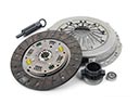 Toyota Clutch Disc
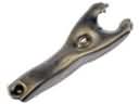 Toyota Clutch Fork
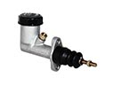 Toyota Clutch Master Cylinder
 Toyota Clutch Release Bearing
 Toyota Clutch Slave Cylinder
 Toyota Flywheel
 Toyota Pilot Bearing
 Toyota Shift Cable
 Toyota Transmission Pan
 Toyota Automatic Transmission Output Shaft Seal
 Toyota Clutch Master Repair Kit