×
ToyotaParts- Hello
- Login or Register
- Quick Links
- Live Chat
- Track Order
- Parts Availability
- RMA
- Help Center
- Contact Us
- Shop for
- Toyota Parts
- Scion Parts
My Garage
My Account
Cart
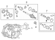
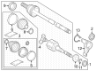
OEM Toyota Transfer Case
Speed Transfer Case- Select Vehicle by Model
- Select Vehicle by VIN
Select Vehicle by Model
orMake
Model
Year
Select Vehicle by VIN
For the most accurate results, select vehicle by your VIN (Vehicle Identification Number).
145 Transfer Cases found

Toyota Transfer Case Part Number: 36100-42160
$2022.56 MSRP: $2520.80You Save: $498.24 (20%)Ships in 1-3 Business DaysProduct Specifications- Other Name: Transfer Assembly; Differential

Toyota Transfer Case Part Number: 36110-35521
$2911.15 MSRP: $3628.29You Save: $717.14 (20%)Ships in 1-3 Business DaysProduct Specifications- Other Name: Transfer Assembly
- Replaces: 36110-35520


Toyota Transfer Case Part Number: 36100-48081
$2469.75 MSRP: $3078.16You Save: $608.41 (20%)Ships in 1-3 Business DaysProduct Specifications- Other Name: Transfer Assembly

Toyota Transfer Case Part Number: 36100-3D471
$2563.27 MSRP: $3194.72You Save: $631.45 (20%)Ships in 1-3 Business DaysProduct Specifications- Other Name: Transfer Assembly
- Replaces: 36100-3D470
Toyota Transfer Case Part Number: 36100-6D411
$2492.22 MSRP: $3106.17You Save: $613.95 (20%)Ships in 1-3 Business DaysProduct Specifications- Other Name: Transfer Assembly
- Replaces: 36100-6D410

Toyota Transfer Case Part Number: 36100-6D401
$2911.15 MSRP: $3628.29You Save: $717.14 (20%)Ships in 1-3 Business DaysProduct Specifications- Other Name: Transfer Assembly
- Replaces: 36100-6D400

Toyota Case Part Number: 36101-32011
$3095.18 MSRP: $4536.03You Save: $1440.85 (32%)Ships in 1-3 Business DaysProduct Specifications- Other Name: Case Sub-Assembly, Transmission; Case Sub-Assembly, Transfer

Toyota Case Sub-Assembly, Transfer Part Number: 36103-52030
$342.15 MSRP: $488.51You Save: $146.36 (30%)Ships in 1-3 Business DaysProduct Specifications- Other Name: Case Sub-Assembly, Transmission

Toyota Transfer Case Part Number: 36100-34100
$1633.39 MSRP: $2035.76You Save: $402.37 (20%)Ships in 1-3 Business DaysProduct Specifications- Other Name: TRANSFER ASSY; Transfer Assembly
- Replaces: 36100-34080

Toyota Transfer Case Part Number: 36110-35111
$1957.23 MSRP: $2439.38You Save: $482.15 (20%)Ships in 1-3 Business DaysProduct Specifications- Other Name: TRANSFER ASSY; Transfer Assembly
Toyota Transfer Case Part Number: 36110-35071
$1957.23 MSRP: $2439.38You Save: $482.15 (20%)Ships in 1-3 Business DaysProduct Specifications- Other Name: TRANSFER ASSY; Transfer Assembly
- Manufacturer Note: W(2-4 SELECTOR)
Toyota Transfer Case Part Number: 36110-35051
$1957.23 MSRP: $2439.38You Save: $482.15 (20%)Ships in 1-3 Business DaysProduct Specifications- Other Name: TRANSFER ASSY; Transfer Assembly
Toyota Transfer Case Part Number: 36110-35031
$2010.09 MSRP: $2505.26You Save: $495.17 (20%)Ships in 1-3 Business DaysProduct Specifications- Other Name: TRANSFER ASSY; Transfer Assembly
- Replaces: 36110-35030

Toyota Transfer Case Part Number: 36100-34171
$2022.56 MSRP: $2520.80You Save: $498.24 (20%)Product Specifications- Other Name: TRANSFER ASSY; Transfer Assembly
- Manufacturer Note: *546
Toyota Transfer Case Part Number: 36110-35060
$2027.63 MSRP: $2527.12You Save: $499.49 (20%)Ships in 1-3 Business DaysProduct Specifications- Other Name: TRANSFER ASSY; Transfer Assembly
- Manufacturer Note: W(*ADD)
Toyota Transfer Case Part Number: 36110-35061
$2073.34 MSRP: $2584.09You Save: $510.75 (20%)Ships in 1-3 Business DaysProduct Specifications- Other Name: TRANSFER ASSY; Transfer Assembly
- Manufacturer Note: W(*ADD)
Toyota Transfer Case Part Number: 36100-34161
$2083.71 MSRP: $2597.03You Save: $513.32 (20%)Product Specifications- Other Name: TRANSFER ASSY; Transfer Assembly
Toyota Transfer Case Part Number: 36110-35351
$2085.74 MSRP: $2599.55You Save: $513.81 (20%)Ships in 1-3 Business DaysProduct Specifications- Other Name: TRANSFER ASSY; Transfer Assembly
- Manufacturer Note: W(*66 & *DL)


Toyota Transfer Case Part Number: 36100-34170
Product Specifications- Other Name: TRANSFER ASSY; Transfer Assembly

Toyota Transfer Case Part Number: 36100-34191
Product Specifications- Other Name: TRANSFER ASSY; Transfer Assembly
| Page 1 of 8 |Next >
1-20 of 145 Results
Toyota Transfer Case
OEM parts deliver unmatched quality you can rely on. They pass extensive quality control inspections. Toyota produces them to the official factory specifications. This process helps prevent defects and imperfections. So you can get exceptional lifespan and a flawless fit. Need new OEM Toyota Transfer Case? You'll love our wide selection of genuine options. Shop in minutes and skip the hunt. Our prices are unbeatable, you'll save time and money. It's easy to shop and find the right piece. Our committed customer service team gives professional help from start to finish. Every part includes a manufacturer's warranty. We ship quickly, your parts will arrive fast at your door.
Toyota Transfer Case is divided into the engine torque between the axles and provides reliable traction on pavement, gravel, or snow. Toyota emerged out of a small company started in 1937 to become a global icon of a lean manufacturer and a tireless waste eliminator. It removes seconds in the assembly operations and provides its employees with the ability to stop the line, ensuring the quality remains high and the prices are realistic. New-found advantages, such as the TNGA platform, stiffen the chassis, reduce center weight, and steer all sedans, hatches, and crossovers with sharp confidence. The reason why drivers are attracted to Toyota hybrids is that the modern Hybrid Synergy Drive powertrains are fuel-stretching, reduce emissions, and do not lose their feel in daily traffic. The plug-in RAV4 of 2024 demonstrates that when electric propulsion is combined with a thumpy gasoline engine, range anxiety can be eliminated. Reliability is the clincher and limitless customers believe Toyota can make it to over 200,000 miles without fanfare. The Transfer Case in each AWD or 4WD model has gears, clutches, and a chain which redirects the power forward to the rear when the driver turns a lever. Part-time logic maintains low fuel consumption under normal running in default two-wheel drive but will lock in solid in the Transfer Case during a rock crawl or unplowed road without hesitation. Separate high and low ranges are mounted on hardened shafts and an electric motor clicks the Transfer Case between ratios quicker than traction control blinkers. That ruggedness allows Toyota owners to have confidence in the Transfer Case on the trail or highways during snowy or rainy weather as the sound of the driveshafts remains minimal after mile after mile.
Toyota Transfer Case Parts and Q&A
- Q: Should the transmission/transfer case assembly be removed before separating them on 2003 through 2009 Toyota 4Runner?A:According to the manufacturer, it is advised that the transmission/transfer case assembly be first removed before they are separated from each other though in some vehicles, the transfer case may be removed with the transmission still connected to the engine. Should the decision be made to retain the transmission then, proper support and lowering methods must be implemented. This should be done by first lifting the vehicle on the jackstands after which the lubricant in the transfer case should be drained. Subsequently, take off the front and rear driveshafts, and then the transfer case breather hose situated on top of the transmission. If required use the scissors to cut off any interfering exhaust pipes. Disconnect all electrical plugs for the vehicle speed sensor and the transfer case position switches before removing the transmission/transfer case assembly. Remove the nuts for the transfer case bolts to the transfer case adapter and an assistant should hold the transfer case pulling it upward from the back of the transmission. Reinstallation occurs in the opposite sequence of the removal process, guaranteeing the transfer case-to-transfer adapter bolts' tightness according to the provided torque. Last, have the vehicle filled with the correct transfer case fluid, take the vehicle for a test drive and check to see whether there is any fluid leakage.
- Q: How to remove the transmission/transfer case assembly on 2005 through 2009 Toyota Tacoma?A:The manufacturer advises that the transmission/transfer case assembly must be pulled out before separating the two but in some cases, the case involves the transfer of the case while the transmission is still attached to the engine. First, bring the car up and safely place it on jackstands starting from the front of the vehicle. Remove the transfer case lubricant then re move the front/rear driveshaft. Any transfer case breather hose should be pulled off from the top of the transmission; exhaust pipes which tended to hinder the transfer case removal were to be removed as well. Remove all the electrical connections particularly the shift actuator wiring and the transfer case position switches. Subsequently, first unbolt the rear retainer of the transmission/transfer case assembly, then, the transfer case can be unbolted from the transmission so that the front of the transmission will rest on the transaxle housing, while using an assistant to support the transfer case during the removal of the bolts in this process. Removal is done in the reverse order of installation and when reconnecting the transfer case-to-transmission bolts, the specified torque has to be tightened again. Lastly, introduce the correct fluid in the transfer case, take the car for a drive so as to observe any cases of leakage.


Related Toyota Parts
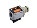 Toyota Shift Solenoid
 Toyota Automatic Transmission Filter
 Toyota Clutch Fork
 Toyota Pilot Bearing
 Toyota Pressure Plate
 Toyota Shift Cable
 Toyota Transmission Drain Plug
 Toyota Transmission Pan
 Toyota Valve Body
 Toyota Automatic Transmission Output Shaft Seal
 Toyota Clutch Hose
 Toyota Clutch Master Repair Kit