×
ToyotaParts- Hello
- Login or Register
- Quick Links
- Live Chat
- Track Order
- Parts Availability
- RMA
- Help Center
- Contact Us
- Shop for
- Toyota Parts
- Scion Parts
My Garage
My Account
Cart
OEM Toyota Echo Pressure Plate
Clutch Pressure Plate- Select Vehicle by Model
- Select Vehicle by VIN
Select Vehicle by Model
orMake
Model
Year
Select Vehicle by VIN
For the most accurate results, select vehicle by your VIN (Vehicle Identification Number).
2 Pressure Plates found


Toyota Echo Pressure Plate Part Number: 31210-52180
$132.18 MSRP: $187.11You Save: $54.93 (30%)Ships in 1-3 Business Days
Toyota Echo Pressure Plate Part Number: 31210-12191-84
Toyota Echo Pressure Plate
Choose genuine Pressure Plate that pass strict quality control tests. You can trust the top quality and lasting durability. Shopping for OEM Pressure Plate for your Toyota Echo? Our website is your one-stop destination. We stock an extensive selection of genuine Toyota Echo parts. The price is affordable so you can save more. It only takes minutes to browse and find the exact fit. Easily add to cart and check out fast. Our hassle-free return policy will keep you stress-free. We process orders quickly for swift delivery. Your parts will arrive faster, so you can get back on the road sooner.
In Toyota Echo vehicles the Pressure Plate for the clutch system proves to be a vital assembly component because of its noted performance and durability. The crucial function of the Toyota Echo Pressure Plate consists of connecting and disconnecting the clutch disc from the flywheel which enables smooth power transmission between engine and transmission. The Toyota Echo Pressure Plate exists in diaphragm and lever forms designed to fulfill different driving conditions through its diaphragm offering lightweight pedal activation during daily use and its lever alternative building resistance for racing and heavy work. Young buyers who seek economical vehicles choose the Toyota Echo which operates with different Echo model combinations to increase its market demand. The Toyota Echo Pressure Plate serves as a key factor in enhancing vehicle performance because it delivers both safety improvements and adaptive gear changes. Belleville springs applied in the diaphragm style of this Pressure Plate serve as an exceptional feature that distinguishes the Toyota car Pressure Plate in the automotive market thus making it the preferred component for drivers seeking durability combined with functional performance. The reliable Pressure Plate from the the automaker model remains memorable to vehicle operators because it provides this vehicle model's distinctive combination of strong performance and competitive price point even though manufacturing of the car ended in 2005.
Toyota Echo Pressure Plate Parts and Q&A
- Q: How to service and repair the pressure plate on Toyota Echo?A:Service and repair of the pressure plate requires engineers to first remove the transaxle from the engine and then remove the clutch cover and disc after aligning the matchmarks between clutch cover and flywheel while slowly loosening each set bolt until spring tension releases before removing the bolts to extract the clutch cover and disc without dropping the Clutch Disc. The procedure starts with uninstalling the release bearing and fork combination then splitting apart each piece followed by removing the release fork support and boot. The examination process requires measuring clutch disc rivet head depth with vernier calipers to verify it surpasses 0.3 mm (0.012 inch) depth; otherwise discard the clutch disc. The clutch disc requires testing using a dial indicator to verify runout falls below 0.8 mm (0.031 inch) while flywheel runout should be less than 0.1 mm (0.004 inch) for replacement purposes. The depth of measurement for the diaphragm spring should not rise beyond 0.5 mm (0.020 inch) and its width beyond 6.0 mm (0.236 inch) and if either limit is reached a new clutch cover needs installation. Examine the release bearing through hand rotation under axial pressure; carry out a replacement when required. Use Special Service Tool: 09301-00210 to install the clutch disc onto the flywheel by placing it correctly and matching its markers with those of the clutch cover and flywheel. The 6 clamping bolts should be tightened according to sequence starting with the knock pin bolt to obtain a torque setting of 19 Nm (195 kgf-cm, 14 ft. lbs.) and achieving equal bolt tension. Verify the disk stays centered. The dial indicator will gauge the diaphragm spring positioning to verify maximum differential is under 0.5 mm (0.020 inch). Use Special Service Tool: 09333-00013 to adjust if needed. The boot and release fork support should be installed onto the transaxle using 37 Nm (375 kgf-cm, 27 ft. lbs.) torque before applying release hub grease (Part No. 08887-01806) at four points: release fork and hub contact, release fork and push rod contact, and release fork pivot points. Complete the installation of the transaxle to the engine by first applying clutch spline grease (Part No. 08887-01706) to the input shaft spline then installing the release bearing to the release fork followed by their placement on the transaxle.

Related Toyota Echo Parts
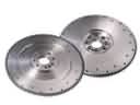 Toyota Echo Flywheel
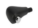 Toyota Echo Automatic Transmission Shift Levers
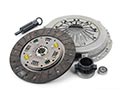 Toyota Echo Clutch Disc
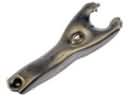 Toyota Echo Clutch Fork
 Toyota Echo Clutch Hose
 Toyota Echo Clutch Master Cylinder
 Toyota Echo Clutch Master Repair Kit
 Toyota Echo Clutch Release Bearing
 Toyota Echo Clutch Slave Cylinder
 Toyota Echo Clutch Slave Repair Kit
 Toyota Echo Torque Converter
 Toyota Echo Transmission Drain Plug