×
ToyotaParts- Hello
- Login or Register
- Quick Links
- Live Chat
- Track Order
- Parts Availability
- RMA
- Help Center
- Contact Us
- Shop for
- Toyota Parts
- Scion Parts
My Garage
My Account
Cart
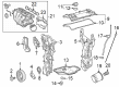
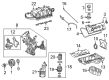
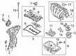
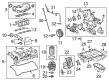
OEM Toyota Intake Manifold
Engine Intake Manifold- Select Vehicle by Model
- Select Vehicle by VIN
Select Vehicle by Model
orMake
Model
Year
Select Vehicle by VIN
For the most accurate results, select vehicle by your VIN (Vehicle Identification Number).
109 Intake Manifolds found


Toyota Manifold, Intake Part Number: 17120-37054
$250.93 MSRP: $358.27You Save: $107.34 (30%)Ships in 1-3 Business DaysProduct Specifications- Other Name: Manifold Assembly, Intake; Intake Manifold
- Manufacturer Note: *119
- Replaces: 17120-37051, 17120-37053, 17120-37052, 17120-37050


Toyota Intake Manifold Part Number: 17120-50020
$1287.08 MSRP: $1886.23You Save: $599.15 (32%)Ships in 1-3 Business DaysProduct Specifications- Other Name: Manifold Assembly, Intake; Engine Intake Manifold; Manifold, Intake
- Replaces: 17120-50010, 17120-50011


Toyota Intake Manifold Part Number: 17120-0T080
$280.87 MSRP: $401.02You Save: $120.15 (30%)Ships in 1-2 Business DaysProduct Specifications- Other Name: Manifold Assembly, Intake; Engine Intake Manifold; Manifold, Intake
- Manufacturer Note: (L)
- Replaces: 17120-37031


Toyota Intake Manifold Part Number: 17101-WAA01
$998.97 MSRP: $1464.00You Save: $465.03 (32%)Ships in 1-3 Business DaysProduct Specifications- Other Name: Manifold Sub-Assembly, Intake; Engine Intake Manifold; Manifold, Intake


Toyota Intake Manifold Part Number: 17101-21080
$137.46 MSRP: $194.60You Save: $57.14 (30%)Ships in 1-3 Business DaysProduct Specifications- Other Name: Manifold Sub-Assembly, Intake; Engine Intake Manifold; Manifold, Intake


Toyota Intake Manifold Part Number: 17120-0T011
$305.92 MSRP: $436.78You Save: $130.86 (30%)Ships in 1-3 Business DaysProduct Specifications- Other Name: Manifold Assembly, Intake; Engine Intake Manifold; Manifold, Intake
- Replaces: 17120-0T010, 17120-37020, 17120-37021


Toyota Intake Manifold Part Number: SU003-06453
$364.07 MSRP: $496.22You Save: $132.15 (27%)Product Specifications- Other Name: Manifold Complete-Intake; Engine Intake Manifold; Manifold, Intake

Toyota Intake Manifold Part Number: 17120-F2010
$277.72 MSRP: $396.53You Save: $118.81 (30%)Product Specifications- Other Name: Manifold Assembly, Intake; Engine Intake Manifold; Manifold, Intake
- Manufacturer Note: *702
- Replaces: 17120-24010

Toyota Manifold, Intake Part Number: 17120-F0060
$383.73 MSRP: $562.36You Save: $178.63 (32%)Ships in 1-3 Business DaysProduct Specifications- Other Name: Manifold Assembly, Intake; Intake Manifold
- Manufacturer Note: *628
- Replaces: 17120-25010, 17120-F0010

Toyota Manifold, Intake Part Number: 17120-38033
$1574.91 MSRP: $2308.06You Save: $733.15 (32%)Ships in 1-3 Business DaysProduct Specifications- Other Name: Manifold Assembly, Intake; Intake Manifold
- Replaces: 17120-38031, 17120-38032, 17120-38030
Toyota Intake Manifold Part Number: 17120-0T012
$221.57 MSRP: $316.35You Save: $94.78 (30%)Ships in 1-2 Business DaysProduct Specifications- Other Name: Manifold Assembly, Intake; Engine Intake Manifold; Manifold, Intake
- Replaces: 17120-37022

Toyota Intake Manifold Part Number: 17120-WB002
$276.86 MSRP: $395.30You Save: $118.44 (30%)Ships in 1-3 Business DaysProduct Specifications- Other Name: Manifold Assembly, Intake; Engine Intake Manifold; Manifold, Intake

Toyota Intake Manifold, Lower Part Number: 17111-0P060
$309.65 MSRP: $442.10You Save: $132.45 (30%)Ships in 1-3 Business DaysProduct Specifications- Other Name: Manifold, Intake; Engine Intake Manifold, Lower
- Position: Lower

Toyota Intake Manifold Part Number: 17120-75043
$362.73 MSRP: $531.59You Save: $168.86 (32%)Ships in 1-3 Business DaysProduct Specifications- Other Name: Manifold Assembly, Intake; Engine Intake Manifold; Manifold, Intake

Toyota Intake Manifold Part Number: 17120-F0020
$383.73 MSRP: $562.36You Save: $178.63 (32%)Ships in 1-2 Business DaysProduct Specifications- Other Name: Manifold Assembly, Intake; Engine Intake Manifold; Manifold, Intake
- Replaces: 17120-25020

Toyota Manifold, Intake, Lower Part Number: 17111-31141
$404.50 MSRP: $592.80You Save: $188.30 (32%)Ships in 1-3 Business DaysProduct Specifications- Other Name: Intake Manifold
- Position: Lower

Toyota Manifold, Intake Part Number: 17120-24020
$399.62 MSRP: $585.65You Save: $186.03 (32%)Ships in 1-3 Business DaysProduct Specifications- Other Name: Manifold Assembly, Intake


Toyota Manifold, Intake, Lower Part Number: 17101-20031
Product Specifications- Other Name: Manifold Sub-Assembly, Intake; Intake Manifold
- Manufacturer Note: (J)
- Position: Lower
- Replaces: 17101-20030, 17101-0A030


Toyota Intake Manifold Part Number: 17120-22010
Product Specifications- Other Name: Manifold Assembly, Intake; Engine Intake Manifold; Manifold, Intake


Toyota Intake Manifold Part Number: 17101-62020
Product Specifications- Other Name: Manifold Sub-Assembly, Intake; Manifold, Intake
| Page 1 of 6 |Next >
1-20 of 109 Results
Toyota Intake Manifold
OEM parts deliver unmatched quality you can rely on. They pass extensive quality control inspections. Toyota produces them to the official factory specifications. This process helps prevent defects and imperfections. So you can get exceptional lifespan and a flawless fit. Need new OEM Toyota Intake Manifold? You'll love our wide selection of genuine options. Shop in minutes and skip the hunt. Our prices are unbeatable, you'll save time and money. It's easy to shop and find the right piece. Our committed customer service team gives professional help from start to finish. Every part includes a manufacturer's warranty. We ship quickly, your parts will arrive fast at your door.
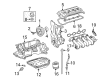
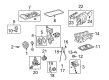
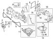
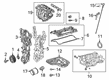
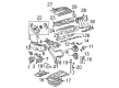
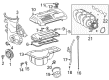
The Toyota Intake Manifold directs air at fresh air with accuracy to raise engine punch and throttle response. Toyota has evolved into an international giant of a company by cutting down on waste, empowering assembly lines, and being obsessed with real-world driving benefits. Toyota continues to introduce hybrids stretching to every gallon such as enhanced Prius Plug-in Hybrid models and an nearly all-electric SUV range that now goes to electric miles. Toyota stretched its TNGA platform to reduce centers of gravity, improve handling, and allow safety technology to be placed in more intelligent locations without overstated expense. Toyota gains long-lasting confidence due to engines that refuse to die, cabins that scorn decades, and ownership costs that are kept down to earth. The Intake Manifold, which is found inside the engine bay, is the traffic cop to airflow splitting the constant oxygen streams to each of the hungry cylinders. A new Intake Manifold crafted of plastic will save weight, resist heat soak, and mold in all runners such that each chamber receives an equal, high-velocity charge. Others are divided into upper and lower shells closed off with gaskets, with coolant passages within the Intake Manifold maintaining the temperatures. Variable length runners allow the Intake Manifold to adjust the speed of airflow to maintain torque high at low RPMs but increase power at high RPMs. Even distribution ensures that every cylinder burns its mixture evenly, enhancing efficiency and cutting off harmful emissions during loads. The mass is also shed off the nose by lightweight construction, making them turn in more quickly and slightly more economical.
Toyota Intake Manifold Parts and Q&A
- Q: How to remove and install Intake Manifold in Four cylinder engine on Toyota Highlander?A:To remove the intake manifold, first relieve the fuel system pressure and disconnect the cable from the negative battery terminal. Next, remove the air intake duct and resonator, followed by the cowl cover assembly. Then, take out the fuel rail and injectors as an assembly. For models from 1999 to 2007, remove the throttle linkage and throttle body from the intake manifold, label and detach the PCV and vacuum hoses connected to the intake manifold, and securely support the vehicle on jackstands. If working on a 4WD model, loosen the right side driveaxle/hub nut and the right front wheel lug nuts before raising the vehicle. Drain the transfer case lubricant, remove the right side driveaxle, and separate the transfer case mount from the transfer case, removing the transfer case mounting brace. For all models, work below the vehicle to remove the manifold lower mounting bolts, then from above, remove the intake manifold upper mounting nuts and bolts, and take out the manifold, gasket, and manifold insulator from the engine. For models from 2008 and later, remove the engine cover, disconnect the vacuum hoses and ventilation tubes from the intake manifold, and remove the throttle body with the electronic throttle actuator. Additionally, remove the windshield wiper motor, brake booster vacuum bracket, and outer cowl top assembly, then disconnect and remove the main harness connector to the intake manifold and tumble control valves. Apply battery voltage to the tumble control valve electrical connector to close the valve, preventing damage during removal. Remove the intake manifold support bracket and disconnect the vacuum switching valve assembly electrical connector, then unscrew the intake manifold mounting fasteners and remove the manifold. For installation, clean the mating surfaces of the intake manifold and cylinder head mounting surface, checking the gasket for leaks and the manifold for warpage. Press a new gasket into the grooves on the intake manifold, install the manifold and gasket over the studs on the cylinder head, and tighten the manifold-to-cylinder head nuts/bolts in three or four equal steps from the center outwards. Reinstall the remaining parts in reverse order, check the coolant level, refill the transfer case for 4WD models, and ensure the throttle linkage operates smoothly before starting the engine to check for coolant and vacuum leaks.
- Q: How to remove and install the intake manifold in V6 engine on 1995 through 2004 Toyota Tacoma?A:Before you make any move of pulling out the intake manifold, get a hold of your stereo's negative terminal then disconnect the battery to get beyond the anti theft system code if there is any. Pump out the coolant into a mixing bucket and then, remove the air cleaner assembly, the throttle body, the fuel injectors and the air intake plenum. It is also important to label all the remaining wires, hoses, and brackets connected to the intake manifold and the coolant outlets with new labels and remove them from the original bundle. Loosen and take off the intake manifold to engine bolts starting from the outside and going to the inside to make sure that the manifold is fully detached from both cylinder heads. Based on the above guidelines, if the manifold is stuck, do not use force and pry between gasket mating surfaces as this will damage them. For installation, scrape off the gasket material and sealant from the manifold and cylinder heads and then wash with lacquer thinner/acetone. New gaskets should be used and the manifold put on the engine; be certain the gaskets stay in position prior to putting the nuts or bolts; starting with the interior bolts and work towards the exterior. Slightly over torque the nuts or bolts in three or four operations, starting with exerting an equal amount of torque from the center in order to avoid distortion. Install the remaining components back in the reverse which it was removed, fill the cooling system and start the engine and check for any fuel or vacuum leakage or any leakage in the coolant.


Related Toyota Parts
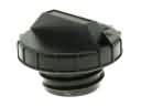 Toyota Gas Cap
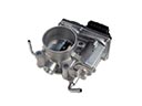 Toyota Throttle Body
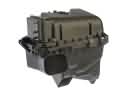 Toyota Air Filter Box
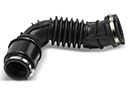 Toyota Air Intake Hose
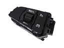 Toyota Cruise Control Switch
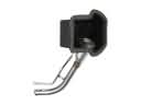 Toyota Fuel Filler Neck
 Toyota Intercooler
 Toyota Air Duct
 Toyota Fuel Filler Hose
 Toyota Fuel Injector O-Rings
 Toyota Fuel Tank Strap
 Toyota Fuel Water Separator Filter
Browse Toyota Intake Manifold by Models
Tacoma 4Runner Camry Tundra Corolla RAV4 Highlander Prius Sienna Land Cruiser Pickup FJ Cruiser 86 Sequoia T100 Avalon Celica Supra Yaris Matrix MR2 Solara Venza GR86 Echo C-HR Cressida Grand Highlander Paseo Previa Prius C Prius Prime Corolla Cross Corolla iM Crown Crown Signia GR Corolla MR2 Spyder Prius V Tercel Yaris iA Prius Plug-In GR Supra Prius AWD-e RAV4 Prime