×
ToyotaParts- Hello
- Login or Register
- Quick Links
- Live Chat
- Track Order
- Parts Availability
- RMA
- Help Center
- Contact Us
- Shop for
- Toyota Parts
- Scion Parts
My Garage
My Account
Cart
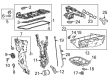
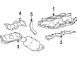
OEM Toyota Land Cruiser Intake Manifold
Engine Intake Manifold- Select Vehicle by Model
- Select Vehicle by VIN
Select Vehicle by Model
orMake
Model
Year
Select Vehicle by VIN
For the most accurate results, select vehicle by your VIN (Vehicle Identification Number).
7 Intake Manifolds found

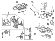
Toyota Land Cruiser Manifold, Intake Part Number: 17120-38033
$1574.91 MSRP: $2308.06You Save: $733.15 (32%)Ships in 1-3 Business Days

Toyota Land Cruiser Manifold Sub-Assembly, Intake Part Number: 17102-50041
$488.83 MSRP: $716.39You Save: $227.56 (32%)Ships in 1-3 Business Days
Toyota Land Cruiser Manifold Assembly, Intake Part Number: 17120-25100
$320.71 MSRP: $457.91You Save: $137.20 (30%)Ships in 1-2 Business Days
Toyota Land Cruiser Manifold, Intake Part Number: 17101-66020
$416.64 MSRP: $610.59You Save: $193.95 (32%)Ships in 1-3 Business Days
Toyota Land Cruiser Intake Manifold Part Number: 17120-50011
$1287.08 MSRP: $1886.23You Save: $599.15 (32%)Toyota Land Cruiser Intake Manifold Part Number: 17111-61040

Toyota Land Cruiser Intake Manifold Part Number: 17101-50040
Toyota Land Cruiser Intake Manifold
Choose genuine Intake Manifold that pass strict quality control tests. You can trust the top quality and lasting durability. Shopping for OEM Intake Manifold for your Toyota Land Cruiser? Our website is your one-stop destination. We stock an extensive selection of genuine Toyota Land Cruiser parts. The price is affordable so you can save more. It only takes minutes to browse and find the exact fit. Easily add to cart and check out fast. Our hassle-free return policy will keep you stress-free. We process orders quickly for swift delivery. Your parts will arrive faster, so you can get back on the road sooner.
Toyota Land Cruiser Intake Manifold Parts and Q&A
- Q: How to install the intake manifold on Toyota Land Cruiser?A:The installation process for the intake manifold starts with mounting the 2 wire harness clamp brackets using 2 bolts which need to be torqued to 8.0 Nm (82 kgf-cm, 71 in-lbf). First align the intake manifold with the purge line hose before installing the purge VSV with a bolt which needs torque application to 21 Nm (214 kgf-cm, 15 ft-lbf). The vacuum switching valve assembly for ACIS needs to be installed on the intake manifold using a bolt that you should torque to 9.0 Nm (92 kgf-cm, 80 in-lbf). Attach the 2 vacuum hoses afterward. Apply the new gasket's protrusion into the intake manifold groove before tightening the Throttle Body with four bolts to 10 Nm (102 kgf-cm, 7 ft-lbf). After installing the bolt for the No. 2 V-bank cover bracket sub-assembly with a torque of 10 Nm (102 kgf-cm, 7 ft-lbf), bolt the V-bank cover to the intake manifold while maintaining the same torque. The installation of the No. 1 V-bank cover bracket requires two bolts that should be torqued to 10 Nm (102 kgf-cm, 7 ft-lbf) followed by the ventilation hose assembly attachment to the intake manifold using two bolts torqued to 21 Nm (214 kgf-cm, 15 ft-lbf) for bolt A and 10 Nm (102 kgf-cm, 7 ft-lbf) for bolt B. Then, place two new gaskets on the intake manifold before positioning it on the cylinder head and uniformly tightening 8 bolts and 2 nuts A bolt connects the wire bracket to the intake manifold where it must be torqued up to 8.0 Nm (82 kgf-cm, 71 in-lbf), while the 3 wire clamps are mounted on the 3 wire brackets. After installing the No. 3 engine cover and the No. 1 engine cover sub-assembly, you should connect the purge VSV connector followed by the purge line hose to the purge VSV, the vacuum switching valve connector for ACIS and the No. 1 ventilation hose together with the 2 water by-pass hoses. The throttle body connector should be joined with the ventilation hose to the ventilation pipe installed on both the cylinder head covers LH and RH. The air cleaner hose assembly installation requires proper positioning of the air cleaner cap protrusion into the hose groove followed by tightening both clamps to 5.0 Nm (51 kgf-cm, 44 in-lbf). Also connect the vacuum hose with the No. 2 ventilation hose. The V-bank cover sub-assembly and No. 1 engine under cover sub-assembly must be installed alongside front fender splash shield sub-assemblies LH and RH and the cowl top ventilator louver sub-assembly. Additionally, adding engine coolant is necessary combined with a negative battery terminal cable connection and throttle body assembly check.

Related Toyota Land Cruiser Parts
 Toyota Land Cruiser Fuel Filter
 Toyota Land Cruiser Fuel Pump
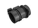 Toyota Land Cruiser Mass Air Flow Sensor
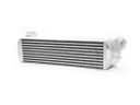 Toyota Land Cruiser Intercooler
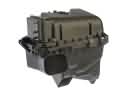 Toyota Land Cruiser Air Filter Box
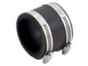 Toyota Land Cruiser Air Intake Coupling
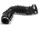 Toyota Land Cruiser Air Intake Hose
 Toyota Land Cruiser Fuel Filler Hose
 Toyota Land Cruiser Fuel Level Sensor
 Toyota Land Cruiser Fuel Pump Seal
 Toyota Land Cruiser Intake Manifold Gasket
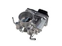 Toyota Land Cruiser Throttle Body