×
ToyotaParts- Hello
- Login or Register
- Quick Links
- Live Chat
- Track Order
- Parts Availability
- RMA
- Help Center
- Contact Us
- Shop for
- Toyota Parts
- Scion Parts
My Garage
My Account
Cart
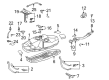
OEM Toyota Fuel Tank
Gas Tank- Select Vehicle by Model
- Select Vehicle by VIN
Select Vehicle by Model
orMake
Model
Year
Select Vehicle by VIN
For the most accurate results, select vehicle by your VIN (Vehicle Identification Number).
212 Fuel Tanks found


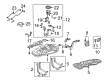
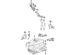
Toyota Fuel Tank Part Number: 77001-08090
$791.88 MSRP: $1160.51You Save: $368.63 (32%)Ships in 1-3 Business DaysProduct Specifications- Other Name: Tank Sub-Assembly, Fuel; Tank Assembly, Fuel


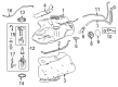
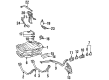
Toyota Fuel Tank Part Number: 77001-52212
$463.52 MSRP: $679.30You Save: $215.78 (32%)Ships in 1-3 Business DaysProduct Specifications- Other Name: Tank Sub-Assembly, Fuel; Tank Assembly, Fuel
- Replaces: 77001-52210, 77001-52211


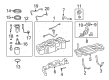
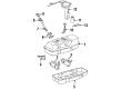
Toyota Fuel Tank Part Number: 77001-0C120
$1128.75 MSRP: $1654.19You Save: $525.44 (32%)Ships in 1-2 Business DaysProduct Specifications- Other Name: Tank Sub-Assembly, Fuel; Fuel Tank Assembly; Tank Assembly, Fuel
- Manufacturer Note: FUEL TANK-38 GALLON


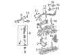
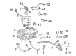
Toyota Fuel Tank Part Number: 77001-47160
$585.31 MSRP: $857.78You Save: $272.47 (32%)Ships in 1-3 Business DaysProduct Specifications- Other Name: Tank Sub-Assembly, Fuel; Tank Assembly, Fuel


Toyota Fuel Tank Part Number: 77001-08080
$714.47 MSRP: $1047.06You Save: $332.59 (32%)Ships in 1-3 Business DaysProduct Specifications- Other Name: Tank Sub-Assembly, Fuel; Tank Assembly, Fuel


Toyota Fuel Tank Part Number: 77001-04201
$724.91 MSRP: $1062.37You Save: $337.46 (32%)Product Specifications- Other Name: Tank Sub-Assembly, Fuel; Tank Assembly, Fuel
- Replaces: 77001-04190, 77001-04200


Toyota Tank Assembly, Fuel Part Number: 77001-0E100
$806.97 MSRP: $1182.63You Save: $375.66 (32%)Ships in 1-3 Business DaysProduct Specifications- Other Name: Tank Sub-Assembly, Fuel; Fuel Tank


Toyota Fuel Tank Part Number: 77001-0C060
$858.84 MSRP: $1258.64You Save: $399.80 (32%)Ships in 1-2 Business DaysProduct Specifications- Other Name: Tank Sub-Assembly, Fuel; Fuel Tank Assembly; Tank Assembly, Fuel
- Replaces: 77001-0C080


Toyota Tank Assembly, Fuel Part Number: 77001-3D510
$1095.83 MSRP: $1605.95You Save: $510.12 (32%)Ships in 1-3 Business DaysProduct Specifications- Other Name: Tank Sub-Assembly, Fuel; Fuel Tank

Toyota Fuel Tank Part Number: 77001-3D931
$642.29 MSRP: $941.28You Save: $298.99 (32%)Ships in 1-3 Business DaysProduct Specifications- Other Name: Tank Sub-Assembly, Fuel
- Replaces: 77001-35997


Toyota Fuel Tank Part Number: 77001-69036
$932.28 MSRP: $1366.26You Save: $433.98 (32%)Ships in 1-3 Business DaysProduct Specifications- Other Name: Tank Sub-Assembly, Fuel W/Plug; Tank Assembly, Fuel
- Replaces: 77001-69035


Toyota Fuel Tank Part Number: 77001-60241
$927.74 MSRP: $1359.61You Save: $431.87 (32%)Ships in 1-3 Business DaysProduct Specifications- Other Name: Tank Sub-Assembly, Fuel


Toyota Fuel Tank Part Number: 77001-34060
$945.33 MSRP: $1385.39You Save: $440.06 (32%)Ships in 1-3 Business DaysProduct Specifications- Other Name: Tank Sub-Assembly, Fuel
- Replaces: 77001-34041

Toyota Fuel Tank Part Number: 77001-34070
$1032.73 MSRP: $1513.47You Save: $480.74 (32%)Ships in 1-3 Business DaysProduct Specifications- Other Name: Tank Sub-Assembly, Fuel
- Replaces: 77001-34042

Toyota Tank Sub-Assembly, Fuel Part Number: 77001-60880
$979.72 MSRP: $1435.79You Save: $456.07 (32%)Ships in 1-3 Business DaysProduct Specifications- Other Name: TANK SUB-ASSY, FUEL; Fuel Tank
- Replaces: 77001-60510, 77001-60660

Toyota Fuel Tank Part Number: 77001-0E051
$636.95 MSRP: $933.46You Save: $296.51 (32%)Product Specifications- Other Name: Tank Sub-Assembly, Fuel; Tank Assembly, Fuel
- Replaces: 77001-0E050, 77001-48130

Toyota Fuel Tank Part Number: 77001-33161
$838.30 MSRP: $1228.54You Save: $390.24 (32%)Ships in 1-3 Business DaysProduct Specifications- Other Name: Tank Sub-Assembly, Fuel
- Replaces: 77001-33160, 77001-06060


Toyota Fuel Tank Part Number: 77001-0R060
$594.96 MSRP: $871.92You Save: $276.96 (32%)Product Specifications- Other Name: Tank Sub-Assembly, Fuel; Tank Assembly, Fuel


Toyota Fuel Tank Part Number: 77001-3D928
Product Specifications- Other Name: Tank Sub-Assembly, Fuel
- Replaces: 77001-359A7


Toyota Fuel Tank Part Number: 77001-04170
Product Specifications- Other Name: Tank Sub-Assembly, Fuel; Tank Assembly, Fuel
| Page 1 of 11 |Next >
1-20 of 212 Results
Toyota Fuel Tank
OEM parts deliver unmatched quality you can rely on. They pass extensive quality control inspections. Toyota produces them to the official factory specifications. This process helps prevent defects and imperfections. So you can get exceptional lifespan and a flawless fit. Need new OEM Toyota Fuel Tank? You'll love our wide selection of genuine options. Shop in minutes and skip the hunt. Our prices are unbeatable, you'll save time and money. It's easy to shop and find the right piece. Our committed customer service team gives professional help from start to finish. Every part includes a manufacturer's warranty. We ship quickly, your parts will arrive fast at your door.
Toyota Fuel Tank has an energy-saving storage to ensure that the energy is preserved in a secure place thereby letting the drivers drive even further without making stressful pit stops. Toyota was started in Japan in 1937 and grew globally through cutting down waste and enabling fast solutions. Toyota maintains high mileage rates and low emissions and expenses result through updates of Hybrid Synergy Drive. The elastic TNGA platform provides Toyota automobiles with reduced maneuverability, more robust bodies, and safer cabins. Pilots get silent starts, extended electric impulses on the RAV4 plug-in and decades of confidence. The constant introduction of hybrids also implies that more models will be drinking fuel rather than guzzling, which is helping the wallet and the air alike. Lean production lines identify defects early, scrap and deliver completed vehicles promptly. Innovation and heritage collide annually but the mission is still the same, produce cars that people can trust. Each Fuel Tank has within it one electric pump and one sender to supply the engine and the dashboard. Fuel Tank baffles reduce the sloshing wave, prevent abrupt change of balance, and reduce the vapor surge. Metal Fuel Tank units are impact resistant but also have the ability to rust, whereas the plastic ones are less corrosive but might also be broken. Upgraded military-grade polymer Fuel Tank choices widen the reach to 500 miles and shake off punctures. That reliability is equal to Toyota emphasis on the cars that last with the trends and the terrain. Baffles are also applied to trap the fumes before they escape when using the evaporative emission system. When correctly shaped, the weight will be placed low, and the car corner will be confident.
Toyota Fuel Tank Parts and Q&A
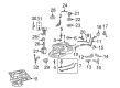
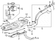
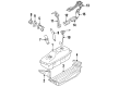
- Q: How to remove the fuel tank on Toyota MR2?A:Relieve the fuel pressure and then disconnect the cable from the negative terminal of the battery. Remove the console and disconnect the electrical connectors for the fuel pump and the fuel gauge sending unit, ensuring to push the connectors and their pigtails through the rubber grommet before removing the fuel tank. Raise the vehicle and secure it on jackstands, then remove the fuel tank protectors, which are the louvered plastic panels bolted to the underside of the vehicle. Disconnect the right parking brake cable bracket from the middle crossmember, slide the cable grommet out of the bracket, and disconnect the right parking brake cable from the equalizer. Remove the parking brake cable support bracket bolts and the middle crossmember bolts, allowing the bracket and crossmember to hang to one side from the remaining parking brake cable. Disconnect the speedometer cable/throttle cable support bracket bolt. Locate the fuel tank filler neck hose and the breather hose at the rear of the fuel tank in the lower front part of the engine compartment, loosen the fuel tank filler hose clamp and the breather hose clamp, and detach the hoses from the fuel tank. Disconnect the fuel feed and return lines, identifying the fuel feed line by its threaded fitting and the return line located above it. Immediately above these lines are the fuel evaporative separator hoses; loosen the hose clamps and detach them. Remove the fuel tank support strap bolts and take the tank out of the vehicle. Installation is the reverse of removal, ensuring to tighten the fuel tank support strap bolts and the fuel feed line threaded fitting to the specified torque.
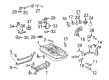
- Q: How to properly remove and reinstall a fuel tank on Toyota Supra?A:Relieve the pressure in the fuel system and disconnect the cable from the negative terminal of the battery. To improve access when working underneath the vehicle, raise the rear end and support it securely on jackstands while blocking the front wheels. Unscrew the drain plug and empty any remaining fuel into an approved fuel container before removing the tank. Pull back the carpet in the luggage compartment, remove the access cover for the fuel level sender unit, and unplug the electrical connector. Disconnect the fuel inlet pipe flange from the fuel tank. Clearly label and then disconnect the fuel outlet, return, and vapor recovery hoses, noting that the outlet hose is the largest in diameter, the return is smaller, and the vapor recovery hose is the smallest. Support the fuel tank with a transmission jack or a floor jack, placing a piece of wood between the jack pad and the tank for protection. Disconnect the tank mounting bands and carefully lower the tank a few inches, ensuring all electrical connectors for the fuel level sender unit or the in-tank fuel pump are disconnected before removing the tank from the vehicle. Installation is the reverse of removal, using a new seal gasket for the sender unit and a new gasket for the fuel filler pipe attachment. Replace any defective or suspect hoses, ensuring that hose and pipe connections are in good condition and secure. Tighten the mounting band retaining nuts securely, then reconnect the fuel level sender unit and fuel pump electrical connectors before reattaching the battery ground cable. Refill the fuel tank and check for any signs of leaks from the tank or from the pipe and hose connections.


Related Toyota Parts
 Toyota Mass Air Flow Sensor
 Toyota Fuel Pump
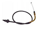 Toyota Accelerator Cable
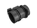
 Toyota Fuel Filler Neck
 Toyota Fuel Pressure Regulator
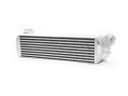 Toyota Intercooler
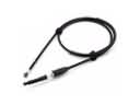 Toyota Throttle Cable
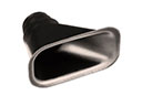 Toyota Air Duct
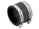 Toyota Air Intake Coupling
 Toyota Fuel Filler Hose
 Toyota Fuel Pump Seal
 Toyota Fuel Pump Wiring Harness
Browse Toyota Fuel Tank by Models
Tacoma 4Runner Camry Tundra Corolla RAV4 Highlander Prius Sienna Land Cruiser Pickup FJ Cruiser 86 Sequoia T100 Avalon Celica Supra Yaris Matrix MR2 Solara Venza GR86 Echo C-HR Cressida Grand Highlander Paseo Previa Prius C Prius Prime Corolla Cross Corolla iM Crown Crown Signia GR Corolla Mirai MR2 Spyder Prius V Starlet Tercel Van Yaris iA Prius Plug-In GR Supra Prius AWD-e RAV4 Prime