×
ToyotaParts- Hello
- Login or Register
- Quick Links
- Live Chat
- Track Order
- Parts Availability
- RMA
- Help Center
- Contact Us
- Shop for
- Toyota Parts
- Scion Parts
My Garage
My Account
Cart
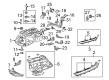
OEM Toyota Highlander Fuel Tank
Gas Tank- Select Vehicle by Model
- Select Vehicle by VIN
Select Vehicle by Model
orMake
Model
Year
Select Vehicle by VIN
For the most accurate results, select vehicle by your VIN (Vehicle Identification Number).
11 Fuel Tanks found


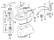
Toyota Highlander Tank Assembly, Fuel Part Number: 77001-0E100
$806.97 MSRP: $1182.63You Save: $375.66 (32%)Ships in 1-3 Business Days
Toyota Highlander Fuel Tank Part Number: 77001-0E051
$636.95 MSRP: $933.46You Save: $296.51 (32%)
Toyota Highlander Fuel Tank Part Number: 77001-0E081
$592.00 MSRP: $867.59You Save: $275.59 (32%)Ships in 1-3 Business Days
Toyota Highlander Fuel Tank Part Number: 77001-0E161
$627.08 MSRP: $918.99You Save: $291.91 (32%)Ships in 1-3 Business Days
Toyota Highlander Tank Sub-Assembly, Fuel Part Number: 77001-48112
$631.84 MSRP: $925.97You Save: $294.13 (32%)Ships in 1-3 Business Days
Toyota Highlander Fuel Tank Part Number: 77001-0E140
$670.09 MSRP: $982.03You Save: $311.94 (32%)Ships in 1-3 Business Days
Toyota Highlander Fuel Tank Part Number: 77001-48152
$671.91 MSRP: $984.69You Save: $312.78 (32%)Ships in 1-3 Business DaysToyota Highlander Fuel Tank Part Number: 77001-0E060
$700.28 MSRP: $1026.27You Save: $325.99 (32%)
Toyota Highlander Fuel Tank Part Number: 77001-48060
$694.61 MSRP: $1017.95You Save: $323.34 (32%)Ships in 1-3 Business Days
Toyota Highlander Tank Sub-Assembly, Fuel Part Number: 77001-0E010
$1035.00 MSRP: $1516.80You Save: $481.80 (32%)Ships in 1-3 Business Days
Toyota Highlander Tank Sub-Assembly, Fuel Part Number: 77001-48230
$659.99 MSRP: $967.22You Save: $307.23 (32%)Ships in 1-2 Business Days
Toyota Highlander Fuel Tank
Choose genuine Fuel Tank that pass strict quality control tests. You can trust the top quality and lasting durability. Shopping for OEM Fuel Tank for your Toyota Highlander? Our website is your one-stop destination. We stock an extensive selection of genuine Toyota Highlander parts. The price is affordable so you can save more. It only takes minutes to browse and find the exact fit. Easily add to cart and check out fast. Our hassle-free return policy will keep you stress-free. We process orders quickly for swift delivery. Your parts will arrive faster, so you can get back on the road sooner.
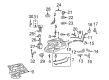
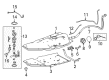
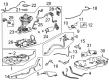
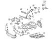
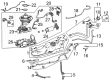
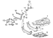
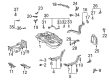
The Fuel Tank of Toyota Highlander vehicles is an essential component of the car that stores the fuel and contains the electric fuel pump as well as fuel gauge sender. It also has a specific function on the so called Evaporative Emission Control System (EVAP) to stop fuel vapors from evaporating. Fuel Tanks used in Highlander are normally constructed with metal or plastic; metal tanks are created through stamping and welding while the plastic Highlander tanks are blow molded HDPE. Corrosive agents affect the metal tanks whereas plastic tanks can crack due to exposure to high heat or vibration. Today, racing fuel tanks have been replaced by fuel cells that will not rupture and spill gasoline in the instance of an accident. Genuine Toyota Highlander replacement fuel tanks with high-capacity made from Mil-Spec polymer provide a much longer driving distance.
Toyota Highlander Fuel Tank Parts and Q&A
- Q: How to replace the fuel tank on Toyota Highlander?A:Before working on the fuel tank you need to drain the fuel system pressure and afterward take away the deck board sub-assembly and rear seat track bracket cover outer along with both left and right rear seat assemblies and rear door scuff plate on the left-hand side and the rear floor service hole cover followed by the fuel suction tube assembly and pump and gauge unit. The propeller with center bearing shaft assembly (4WD type) must be removed together with Exhaust Pipe assembly center and front floor heat insulator No.3 and exhaust pipe support bracket No.4 (4WD type) requires removing 2 bolts to proceed. The sequential steps involve removing the first fuel tube protector by taking off its 2 clips and unscrewing the claw before moving to the first fuel tank protector followed by its assembly No.1 through disassembly of 4 nuts with 3 clips ( 1) and 6 nuts. To disconnect the fuel pump tube you can remove the lock claws by pinching the retainer projection until they unlock and pull the tube out while maintaining a clean state of the connector. Unfasten the fuel tank to filler pipe hose by loosening its hose clamp bolt before disassembling the fuel tank vent hose and breather tube No.3. Set the transmission jack below the fuel tank before removing the 4 bolts and 2 fuel tank bands along with the 2 nuts to operate the jack for fuel tank removal. Extract the combination of fuel pump tube sub-assembly with the fuel tank to filler pipe hose alongside the fuel tank vent hose while taking out the tank suction tube support and fuel tank side plate and fuel tank cushion set. Set the new fuel tank cushion set alongside the side plate before torquing to 30 N.m (306 kgf.cm, 22 ft.lbf); thereafter insert the tank suction tube support along with the fuel tank vent hose and fuel tank to filler pipe hose. Set the transmission jack under the fuel tank assembly then torque two fuel tank bands with 4 bolts to 39 N.m and two nuts to 20 N.m. Neatly connect the components which include fuel tank wire connector and fuel tank to filler pipe hose together with fuel tank breather tube No. 3 and fuel tank vent hose while verifying all attachments are tight. Begin by clicking the quick connector into place and afterward install sub-assembly No.1 and its attached 6 nuts with torque to 5.5 N.m (56 kgf.cm, 49 in.lbf) in addition to the 3 new retainers before installing parts No.1 and No.1. Reposition and torque the exhaust pipe support bracket No.4 (4WD type) to 22 N.m (224 kgf.cm, 16 ft.lbf) along with front floor heat insulator No.3 and exhaust pipe assembly center. After filling the tank with fuel install the pump gauge assembly onto the suction tube before checking for any gas or fuel leaks. The last step involves reinstalling the rear floor service hole cover, followed by both rear door scuff plate left-hand side pieces, rear seat assemblies (both left and right), and rear seat track bracket cover outer. Deck board sub-assembly installation comes next, then the propeller with center bearing shaft assembly (4WD type) then a full tightening of the propeller assembly. Transfer oil (4WD type) addition follows before an inspection of transfer oil (4WD type).

Related Toyota Highlander Parts
 Toyota Highlander Fuel Filter
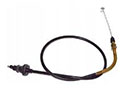 Toyota Highlander Accelerator Cable
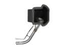 Toyota Highlander Fuel Filler Neck
 Toyota Highlander Fuel Line Clamps
 Toyota Highlander Fuel Pressure Regulator
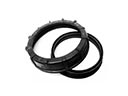 Toyota Highlander Fuel Pump Seal
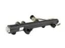 Toyota Highlander Fuel Rail
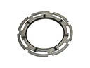 Toyota Highlander Fuel Tank Lock Ring
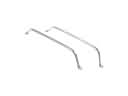 Toyota Highlander Fuel Tank Strap
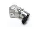 Toyota Highlander Idle Control Valve
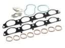 Toyota Highlander Intake Manifold Gasket
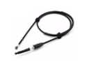 Toyota Highlander Throttle Cable