×
ToyotaParts- Hello
- Login or Register
- Quick Links
- Live Chat
- Track Order
- Parts Availability
- RMA
- Help Center
- Contact Us
- Shop for
- Toyota Parts
- Scion Parts
My Garage
My Account
Cart
OEM Scion Rack And Pinion
Steering Gear- Select Vehicle by Model
- Select Vehicle by VIN
Select Vehicle by Model
orMake
Model
Year
Select Vehicle by VIN
For the most accurate results, select vehicle by your VIN (Vehicle Identification Number).
10 Rack And Pinions found


Scion Gear Assembly, Steering Part Number: 45510-75030
$747.50 MSRP: $1095.48You Save: $347.98 (32%)Ships in 1-3 Business DaysProduct Specifications- Other Name: Steering Gearbox


Scion Steering Gear, Driver Side Part Number: SU003-00841
$230.47 MSRP: $306.02You Save: $75.55 (25%)Ships in 1-2 Business DaysProduct Specifications- Other Name: Gear Box Assembly M/S Left-Hand; Rack and Pinion Assembly; Steering Gearbox; Gear Assembly; Gear Assembly, Steering
- Position: Driver Side


Scion Steering Gear Part Number: 45510-12640
$568.96 MSRP: $833.82You Save: $264.86 (32%)Ships in 1-3 Business DaysProduct Specifications- Other Name: Gear Assembly, Steering; Rack and Pinion Assembly; Steering Gearbox; Gear Assembly

Scion Gear Assembly Part Number: 45510-12471
$608.35 MSRP: $891.54You Save: $283.19 (32%)Ships in 1-3 Business DaysProduct Specifications- Other Name: Gear Assembly, Steering; Rack and Pinion Assembly; Steering Gearbox; Steering Gear Assembly
- Replaces: 45510-12470

Scion Gear Assembly Part Number: 44200-21123
$722.42 MSRP: $1058.70You Save: $336.28 (32%)Ships in 1-3 Business DaysProduct Specifications- Other Name: Link Assembly, Power Steering; Rack and Pinion Assembly; Steering Gearbox; Steering Gear Assembly
- Replaces: 44200-21122, 44200-21120, 44200-21121

Scion Steering Gear Part Number: 45510-WB006
$476.48 MSRP: $698.29You Save: $221.81 (32%)Ships in 1-2 Business DaysProduct Specifications- Other Name: Gear Assembly, Steering; Rack and Pinion Assembly; Steering Gearbox; Gear Assembly
- Replaces: 45510-WB002

Scion Gear Assembly Part Number: 45510-52211
$582.13 MSRP: $853.12You Save: $270.99 (32%)Ships in 1-3 Business DaysProduct Specifications- Other Name: Gear Assembly, Steering; Rack and Pinion Assembly; Steering Gearbox; Steering Gear Assembly
- Replaces: 45510-52210

Scion Steering Gear Part Number: 45510-74020
$624.69 MSRP: $915.49You Save: $290.80 (32%)Ships in 1-3 Business DaysProduct Specifications- Other Name: Gear Assembly, Steering; Rack and Pinion Assembly; Steering Gearbox; Gear Assembly
Scion Gear Assembly Part Number: 45510-52191
$626.62 MSRP: $918.32You Save: $291.70 (32%)Ships in 1-3 Business DaysProduct Specifications- Other Name: Gear Assembly, Steering; Rack and Pinion Assembly; Steering Gearbox; Steering Gear Assembly
- Replaces: 45510-52190

Scion Steering Gear Part Number: 44200-52340
$610.09 MSRP: $894.08You Save: $283.99 (32%)Ships in 1-3 Business DaysProduct Specifications- Other Name: Rack and Pinion Assembly; Steering Gearbox; Gear Assembly; Steering Gear Assembly; Link Assembly, Power Steering
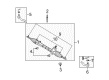
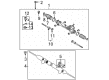
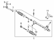
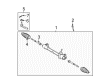
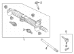
Scion Rack And Pinion
OEM parts deliver unmatched quality you can rely on. They pass extensive quality control inspections. Scion produces them to the official factory specifications. This process helps prevent defects and imperfections. So you can get exceptional lifespan and a flawless fit. Need new OEM Scion Rack And Pinion? You'll love our wide selection of genuine options. Shop in minutes and skip the hunt. Our prices are unbeatable, you'll save time and money. It's easy to shop and find the right piece. Our committed customer service team gives professional help from start to finish. Every part includes a manufacturer's warranty. We ship quickly, your parts will arrive fast at your door.
Scion Rack And Pinion converts the steering input into the sharp movement of the wheel, providing drivers with fast and confident control. Born in 2003, the brand courted young consumers with outrageous paint, no-haggles pricing and Release Series drops that made any purchase seem like grabbing rare sneakers. Scion did not spend money on expensive television advertising and created hype with virtual Scion City and live music where the badge was met by the fans themselves. The simple nature of the options and the tightness of the lineup allowed Scion to make first-time buyers take as much time as they needed to personalize the colors and the audio system as opposed to having to negotiate with the invoices. Scion went out in 2016, but its rogue purchasing concept continues to inform parent designs in search of playful and sincere value. In this type of steering, a straight gear is attached to a rack and the small wheel rotation is translated into sharp lateral motion at the tires. The hydraulic assist in the Rack And Pinion provides some muscle during parking speeds and loosens on the highway, combining comfort with the feel. Straight gears allow the Rack And Pinion to fight against wear and provide truthful information through the wheel when long and difficult drives are involved. Several different models take the identical Rack And Pinion, thus allowing owners to switch or upgrade without searching to find unusual pieces.
Scion Rack And Pinion Parts and Q&A
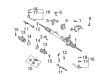
- Q: How to install the Rack And Pinion on Scion tC?A:Special Service Tool: 09023-38201 enables the left-turn pressure tube installation by implementing 22 Nm (224 kgf-cm, 16 ft-lbf) torque when using a torque wrench with 300 mm (11.81 in.) fulcrum length and parallel alignment. Repeat the same procedure for the right-turn pressure tube. Reapply the same torque specifications to install and torque the right turn pressure tube. The installation of the power rack and pinion link assembly requires torqueing its 4 bolts to 49 Nm (500 kgf-cm, 36 ft-lbf) after fixing the assembly using 4 bolts and 4 nuts without rotating the nuts. After aligning matchmarks between the intermediate and pinion shafts install the bolt by torquing it to 35 Nm (357 kgf-cm, 26 ft-lbf). Afterward, install the No. 1 rack and pinion column hole cover sub-assembly along with the front suspension crossmember sub-assembly while employing a transmission jack to support it and fasten it with 2 nuts at 133 Nm (1,356 kgf-cm, 98 ft-lbf). Secure both sides of the crossmember brackets using specified torque values for each bolt before fixing the engine mounting insulator rear with a bolt alongside 3 nuts at 65 Nm (663 kgf-cm, 48 ft-lbf). The assembly requires installation of four bolts which require specific torque values. Proceed by attaching 2 bolts to hook No. 1 through 39 Nm torque (398 kgf-cm, 29 ft-lbf). Proceed with connecting both front suspension arm sub-assemblies before joining the front stabilizer link assemblies. To connect the pressure feed tube assembly use Special Service Tool: 09023-12701 at 41 Nm (414 kgf-cm, 30 ft-lbf) while applying a bolt with secured torque at 7.8 Nm (80 kgf-cm, 69 in-lbf). After connecting both tie rod end sub-assemblies the installer should move on to install the exhaust pipe assembly center and the front floor panel brace. The installation of front wheels requires 103 Nm (1,050 kgf-cm, 76 ft-lbf), then connect the No. 1 rack and pinion column hole cover sub-assembly followed by the No. 2 rack and pinion intermediate shaft assembly with 35 Nm (357 kgf-cm, 26 ft-lbf) torque while maintaining proper alignment. Insert the Front Rack And Pinion Column Hole Silencer Sheet while installing the No. 1 Engine Cover Sub-Assembly and perform power steering fluid addition followed by bleeding the system then check reservoir fluid levels before inspecting for leakage. As the last step install the hood sub-assembly before performing front wheel alignment inspection and installing engine under covers on both sides.
- Q: How to Overhaul a Power Steering Rack and Pinion Assembly on Scion xB?A:The process of power steering link assembly overhaul starts by using special tool 09631-10041 to tighten the rack and pinion over the housing rack while applying power steering fluid to the tool. The installer should inspect the rack and pinion teeth end for any burrs which need removing before moving forward. Following correct installation of the oil seal requires usage of special service tool: 09950-60010 (09951-00210, 09951-00340, 09952-06010), 09950-70010 (09951-07100) and a press. The procedure includes rack bush oil seal installation onto rack bush using appropriate tools with correct oil seal placement, application of power steering fluid to a new O-ring, and protection of the oil seal lip by wrapping the rack and pinion end with vinyl tape before rack bush insertion into the rack housing. First add the cylinder end stopper followed by installation of the hole snap ring using needle nose pliers. The rack housing requires special service tool: 09631-12071 (09633-00010) for an air tightness test. Apply a 53 kPa (400 mm Hg, 15.75 inch Hg) vacuum for 30 seconds to check whether the vacuum changes. Address any oil seal failure during this process. The procedure requires application of grease to the needle roller bearing followed by installation of a new gasket to the rack housing. The next step involves aligning matchmarks before installing the control valve housing with control valve to the rack housing through 2 bolts which must be torqued to 21 Nm (214 kgf-cm, 15 ft. lbs.). After integrating the rack guide with spring spacer and spring, ensure proper placement of the spacer and apply sealant (Part No. 08833-00080, Three Bond 1344, Loctite 242 or equivalent) to 2 or 3 threads of the rack guide spring cap. Then temporarily fasten the cap. Install the RH and LH rack ends sub-assembly before you torque the rack guide spring cap to 25 Nm (250 kgf-cm, 18 ft. lbs.) using a hexagon wrench (19 mm) while returning the cap approximately 12 degrees and utilizing special service tool: 09616-00011 to turn the control valve. Set the rack guide spring cap preload to 1.2 to 1.5 Nm (12 to 15 kgf-cm, 10.6 to 13.3 inch lbs.) by tightening the cap after the spring stops functioning, then apply sealant to the cap lock nut threads, install the nut briefly and torque it to 28 Nm (286 kgf-cm, 21 ft. lbs.) using special service tool: 09922-10010. Recheck the complete preload and unassemble the RH and LH rack ends sub-assembly. Install both rack end sub-assemblies for a temporary period and torque them to 60 Nm (614 kgf-cm, 44 ft. lbs.) through the use of special service tool: 09922-10010 while ensuring the proper direction of the tool. Apply silicon grease to the inside small caliber of rack boot No.2 before installing the boot onto the rack housing while avoiding damage or boot twist. First secure rack boot No.1 with special service tools: 09240-00020, 09521-24010 which should produce a 3.0 mm (0.118 inch) or less gap. Perform the same tightening procedure for rack boot No.1 clamp. Use pliers to install the boot clips before securing the lock nut and tie rod end subassembly LH to the rack end subassembly until matchmarks align and torquing the connection to 74 Nm (750 kgf-cm, 54 ft. lbs.). Follow the same procedure for the RH side. Reinstall the right turn pressure tube to the power steering link assembly with special service tool: 09023-38201 and torque the connection to 12 Nm (118 kgf-cm, 9 ft. lbs.). Pursue the same installation procedure for left turn pressure tube. After matching the marks on grommet No.2 with the power steering link assembly you should install bracket No.2 with its inscribed mark facing forward before tightening the 4 bolts and nuts to 74 Nm (749 kgf-cm, 54 ft. lbs) with fixed nut position. Position the steering intermediate shaft with matchmarks aligned and bolt it until it reaches a tightness of 28 Nm (290 kgf-cm, 21 ft. lbs.). Fasten the power steering rack housing heat insulator through its bolt while tightening it to 18 Nm (178 kgf-cm, 13 ft. lbs.). Additionally secure the bolt that attaches the heat insulator with a torque of 35 Nm (360 kgf-cm, 26 ft. lbs.). Set the transmission jack beneath the front suspension crossmember sub-assembly and use special service tool: 09670-00010 to align the holes before installing the assembly with 4 bolts and tightening Bolt A to 116 Nm (1,183 kgf-cm, 86 ft. lbs.) and Bolt B to 70 Nm (714 kgf-cm, 52 ft. lbs.), while also installing the crossmember with a bolt and 2 nuts torqued to 72 Nm (734 kgf-cm, 53 ft. lbs.) and the 2 reinforcements with 4 bolts torqued The first installation step includes the lower front suspension arm sub-assemblies No.1 LH and RH while connecting the pressure feed tube assembly through special service tool: 09023-12701 requiring a torque specification of 27 Nm (273 kgf-cm, 20 ft. lbs.). Additionally, complete the assembly by attaching the return hose with its clip before installing the tube clamp on the crossmember sub-assembly using bolts torqued to 7.8 Nm (80 kgf-cm, 69 inch lbs.). Follow installation of sub-assemblies for front tie rod ends which requires wheel torque application of 103 Nm (1,050 kgf-cm, 76 ft. lbs.). Install the steering sliding yoke sub-assembly through matching the marks while bolting it to 28 Nm (290 kgf-cm, 21 ft. lbs.). Inspect the center front wheel, install the steering column hole cover sub-assembly No.1, add power steering fluid, bleed the power steering fluid, check the fluid level in the reservoir, inspect for fluid leaks, install the hood sub-assembly, adjust the hood sub-assembly, inspect and adjust front wheel alignment, install the engine under cover LH and RH, install the cowl panel sub-assembly, install the windshield wiper motor & link assembly, install the cowl top ventilator louver LH and RH, install the hood to cowl top seal, and finally install the front wiper arms LH and RH.