×
ToyotaParts- Hello
- Login or Register
- Quick Links
- Live Chat
- Track Order
- Parts Availability
- RMA
- Help Center
- Contact Us
- Shop for
- Toyota Parts
- Scion Parts
My Garage
My Account
Cart
OEM Scion xA Rack And Pinion
Steering Gear- Select Vehicle by Model
- Select Vehicle by VIN
Select Vehicle by Model
orMake
Model
Year
Select Vehicle by VIN
For the most accurate results, select vehicle by your VIN (Vehicle Identification Number).
1 Rack And Pinion found

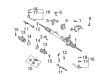
Scion xA Steering Gear Part Number: 44200-52340
$610.09 MSRP: $894.08You Save: $283.99 (32%)Ships in 1-3 Business Days
Scion xA Rack And Pinion
Choose genuine Rack And Pinion that pass strict quality control tests. You can trust the top quality and lasting durability. Shopping for OEM Rack And Pinion for your Scion xA? Our website is your one-stop destination. We stock an extensive selection of genuine Scion xA parts. The price is affordable so you can save more. It only takes minutes to browse and find the exact fit. Easily add to cart and check out fast. Our hassle-free return policy will keep you stress-free. We process orders quickly for swift delivery. Your parts will arrive faster, so you can get back on the road sooner.
Scion xA Rack And Pinion is a definite part that impacts the performance of the Scion xA car which is known for its reliability. This system is used in turning the steering wheel's rotational movement into linear output in the form of lateral movement of the front wheels to meet the demanded dynamics. Most of the Scion xA models have positive power easing Rack And Pinion steering systems that incorporate hydraulic systems to ease the steering to enable the driver to maneuver tough terrains. Besides increasing efficiency, it purposefully ensures that the response of the steering is more precise and safe. The versatility of the Rack And Pinion system allows Scion xA drivers with this version to drive with ease since the models are compatible. It is important to take your Scion xA Rack And Pinion for repairs at least once every now and then because the rack and pinion would most often than not develop holes in it or would just get stiff resulting in a defect in the steering system. Thus, Scion xA had many advantages in a segment of automobiles, while its high fuel efficiency coefficients and performance characteristics are combined with a rational and versatile equipment, such as four-wheel disc brakes with anti-lock systems and traction control. All these combine and supplement the Rack And Pinion to provide a safe and enjoyable drive, which makes the Scion xA a reliable car for subcompact category.
Scion xA Rack And Pinion Parts and Q&A
- Q: How to remove the Rack And Pinion on Scion xA?A:Start power steering link removal by taking out the front wiper arms (right-hand side and left-hand side) then remove the hood to cowl top seal and both cowl top ventilator louvers also located on the right-hand side and left-hand side of the vehicle. Proper sequence begins with removing the windshield Wiper Motor assembly along with its links until cowl panel units are removed. The first step is to check the center front wheel then remove both the steering column hole cover plate and steering sliding yoke subassembly by securing the steering wheel to the Seat Belt to stop rotation and protect the spiral cable from damage. Next mark the sliding yoke and intermediate shaft before loosening the bolt to finally detach the sliding yoke from the intermediate shaft. Remove clip A to disconnect the No. 1 steering column hole cover sub-assembly while safeguarding clip B from damage. Execute the removal of the hood assembly, empty the power steering fluid, then detach both front wheels. The tie rod end sub-assemblies need to be disconnected from both sides using identical procedures. To begin the replacement procedure of the pressure feed tube assembly you will need to unfasten the clip and return hose before using Special Service Tool: 09023-12701 to separate the pressure feed tube and remove the return tube. The following step entails removing the bolt and disconnecting the tube clamp. Apply the same procedures to both sides for disconnecting No. 1 front suspension arm sub-assemblies (lower LH and RH) from the vehicle. After suspension the engine assembly can be completed by installing 2 No. 1 engine hangers (Parts No. The engine suspension requires two No. 1 engine hangers (parts No.: No. 1 engine hanger: 12281-21010 Bolt: 91642-81025) with a tightening torque at 40 Nm (408 kgf-cm, 30 ft. lbs.) to hold the engine using a sling device and chain hoist while avoiding any attachment that would suspend the engine through connected chain parts. The technician needs to detach the front suspension crossmember sub-assembly by first removing four bolts along with two reinforcements before completing the process by unbolting the engine mounting insulator rear but always stabilizing the crossmember with a transmission jack while removing its four bolts and the crossmember itself. Begin by unbolting the 2 bolts securing the power steering rack and pinion housing heat insulator and extracting the insulator which leads to removal of the No. 1 steering column hole cover sub-assembly and the steering intermediate shaft. Mark both the steering link and intermediate shaft before disconnecting the bolt and intermediate shaft. Mark the steering link and No. 2 bracket before removing 4 bolts, nuts, No. 2 bracket and No. 2 grommet and steering link. Torque the bolt with the nut fixed because the nut possesses its own stopper that prevents turning the bolt. You must remove the steering turn pressure tube RH by using Special Service Tool: 09023-38201 and extract its 2 O-rings then carry out the exact procedure for the left steering turn pressure tube.

Related Scion xA Parts
 Scion xA Power Steering Pump
 Scion xA Drag Link
 Scion xA Ignition Switch
 Scion xA Power Steering Hose
 Scion xA Power Steering Reservoir
 Scion xA Rack and Pinion Boot
 Scion xA Steering Angle Sensor
 Scion xA Steering Column
 Scion xA Steering Shaft
 Scion xA Steering Wheel
 Scion xA Tie Rod End
 Scion xA Windshield Wiper Switch