- Hello
- Login or Register
- Quick Links
- Live Chat
- Track Order
- Parts Availability
- RMA
- Help Center
- Contact Us
- Shop for
- Toyota Parts
- Scion Parts

Popular OEM Scion xA Parts
- Body & Hardware Parts View More >
- Electrical Parts View More >
- Engine Parts View More >
- Air & Fuel Delivery Parts View More >
- Belts & Cooling Parts View More >
- Steering Parts View More >
- Suspension Parts View More >
- Emission Control & Exhaust Parts View More >
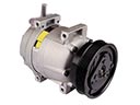
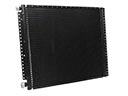
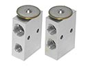
- A/C & Heating Parts View More >
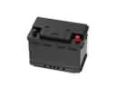
- Charging & Starting Parts View More >
- Brakes Parts View More >
- Transmission Parts View More >


Why Buy Genuine Scion xA Parts From ToyotaPartsNow.com
ToyotaPartsNow.com highlights the reliability of OEM Scion xA parts right at your fingertips. Our skilled staff assists customers in selecting the right Scion xA parts and provides expert help with any unique part requests. At ToyotaPartsNow.com, we make all Scion xA parts available to you quickly and efficiently through our fast order and reliable ship process. Our service is designed to make finding the correct Scion xA parts fast and easy whether you are an amateur or a professional. We offer access to a broad inventory that includes a wide range of Scion years and variants. Affordable prices, quick processing and professional service are also our specialty to ensure your car remains in top condition with OEM Scion xA parts. You can feel confident shopping with us because all Scion xA parts you purchase from our store are of genuine quality and built to last.
The Scion xA experienced manufacturing from June 2003 through December 2006 period during which its innovative engineering and distinctive design elements met the market demands. The Toyota Vitz (Yaris) platform enabled Scion xA to produce a 1.5-liter four-cylinder engine with variable valve timing which delivered 103 horsepower to support urban driving and highway traveling. Enhanced driving performance comes from the five-speed manual transmission because this transmission provides effective and user-friendly operation. Standard antilock brakes paired with electronic brakeforce distribution find place in the Scion xA while optional side airbags and head curtain airbags support its four-star crash test result. The 2006 Scion received updated bumpers together with new side panels as well as steering wheel speakers which reflected its modern design approach. Factory standards enforce that Scion xA genuine parts deliver performance quality standards which keep the vehicle structurally compatible. An individual buyer seeking a vehicle specifically chooses the Scion xA because it provides durable construction along with forty dealer-installed customization options. The Scion xA has secured its position in automotive history because its combination of design characteristics and safety elements led to the halt of production but continued to deliver driving enjoyment.
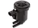
Some of the problems likely to face Scion xA concern problems that are mechanical in nature, especially when it comes to the engine, electrical system, and the braking system. A defective Scion xA VVT-i controller is a common cause of an illuminated Check Engine Light. The Scion xA component is applied to adjust the timing of the cam timing to deliver the maximum amount of power, and replacing it with a new component can resolve the situation. The air conditioning system is also another issue that might not blow cold air because of a wrongly adjusted blend door cable. Correct cable adjustment will restore the desired temperature. Besides, the driver could hear a squeaking sound upon trying out the brakes in reverse. The problem is caused by the brake pads and may be solved by applying differently shaped Scion xA brake pads, anti-squeal shims, and applying more brake grease during the assembly process. All these parts have an impact on the performance and comfort of the Scion xA, and all of them should be fixed at the proper time to preserve the reliability of the car. By regularly addressing such problems and responding to them promptly, you can ensure the effective functioning of the Scion xA.
Scion xA Parts and Q&A
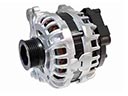
- Q: How to remove and install an alternator on Scion xA?A:In order to change the alternator, disconnect the negative battery terminal and wait 90 seconds. Take off generator assembly, loosen the bolts and dismount the V-belt. Installation: The generator and V-belt should be secured, tension adjusted and bolts tightened. Re-connecting the battery and carrying out an initialisation of some systems.
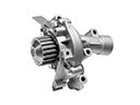
- Q: How to replace the water pump assembly on Scion xA?A:To change the water pump assembly, drain the coolant, remove the fan and generator V-belt and engine mounting insulator RH. Get a special tool to grasp the pulley and then take it out along with the water pump. Installation: place in the new pump and gasket, torque bolts and replacement components and check that there are no leaks.
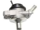
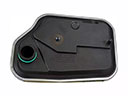
- Q: How to replace the oil filter sub-assembly safely and correctly on Scion xA?A:To change the oil filter sub-assembly, do not take excessive time in contact with engine oil. Use protective clothing and gloves, and ablate the skin. Should used oil and filters be disposed of properly. Drain engine oil, pull off and change filter and verify leakage after refilling.


