×
ToyotaParts- Hello
- Login or Register
- Quick Links
- Live Chat
- Track Order
- Parts Availability
- RMA
- Help Center
- Contact Us
- Shop for
- Toyota Parts
- Scion Parts
My Garage
My Account
Cart
OEM Scion xA Axle Shaft
Car Axle Shaft- Select Vehicle by Model
- Select Vehicle by VIN
Select Vehicle by Model
orMake
Model
Year
Select Vehicle by VIN
For the most accurate results, select vehicle by your VIN (Vehicle Identification Number).
4 Axle Shafts found

Scion xA Axle Assembly, Front Driver Side Part Number: 43420-52071
$370.23 MSRP: $542.57You Save: $172.34 (32%)Ships in 1-3 Business Days
Scion xA Axle Assembly, Front Passenger Side Part Number: 43410-52071
$414.04 MSRP: $606.77You Save: $192.73 (32%)Ships in 1-3 Business Days
Scion xA Outer Joint Assembly, Driver Side Part Number: 43470-59456
$212.25 MSRP: $303.05You Save: $90.80 (30%)Ships in 1-3 Business Days
Scion xA Outer Joint Assembly Part Number: 43460-59367
$251.16 MSRP: $358.61You Save: $107.45 (30%)Ships in 1-3 Business Days
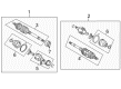
Scion xA Axle Shaft
Choose genuine Axle Shaft that pass strict quality control tests. You can trust the top quality and lasting durability. Shopping for OEM Axle Shaft for your Scion xA? Our website is your one-stop destination. We stock an extensive selection of genuine Scion xA parts. The price is affordable so you can save more. It only takes minutes to browse and find the exact fit. Easily add to cart and check out fast. Our hassle-free return policy will keep you stress-free. We process orders quickly for swift delivery. Your parts will arrive faster, so you can get back on the road sooner.
Scion xA Axle Shaft is one of the highly dependable and trusted parts that are effectively involved in the important procedure of transmitting power from the differential to the drive wheels. This design helps Scion xA to have better tractions during cornering as well as have different speeds for each wheels. Standard parts of Scion xA Axle Shaft is manufactured from Chrome-molybdenum or carbon steel but other types could be made from alloy steel or other stronger materials to enhance its durability. Designed for the Scion xA, this axle shaft is a part of a halfshaft system of a car that needs to interconnect between the transaxle and the wheel hubs with the use of CV joints because it has an independent suspension system. Besides improving the comfort of a car, this configuration helps to increase safety and performance of the vehicle. In general, it is recommended that the Scion xA Axle Shaft be serviced regularly as noisy or vibrating CV joints or bearings of the axle can indicate it's time to get it fixed. The Scion xA is a winner on this front as well offering an amazing fuel economy of 27 / 34 mpgCity/Highway respectively, making it a sensible addition in the showrooms. The Scion xA Axle Shaft also has interesting features as four-wheel disc brakes, traction control and comfortable interior which creates a key in the automotive market so that the drivers can enjoy a reliable and efficient drive.
Scion xA Axle Shaft Parts and Q&A
- Q: How to overhaul the axle shaft on Scion xA?A:Start front drive shaft overhaul by draining manual transaxle oil with 39 Nm torque and automatic transaxle fluid with 25 Nm torque. The procedure begins with removing the engine under cover LH and the front wheel before using Special Service Tool: 09930-00010 and a hammer to pry up retaining tabs on the front axle hub LH nut. Freeing up the staked part prevents damage to drive shaft screw screws. The procedure requires you to apply vehicle brake pressure before discontinuing the hub LH nut. Before detachment of the Speed Sensor front LH the bolt must be removed and clip taken off while disassociating it from Shock Absorber assembly front LH and steering knuckle with an emphasis on sensor protection. After holding the bolt with a spanner (10 mm) remove the nut and proceed to separate the stabilizer bar front while doing the same with the two cushion retainers No.1 and the two cushions. Next remove the clip and the nut on the front suspension arm sub-assembly lower-No.1-LH while using Service Special Tool 09628-00011 to separate it from the steering knuckle. When working on the tie rod end sub-assembly LH remove the cotter pin and nut then employ Special Service Tool: 09628-62011 to perform the separation from the steering knuckle. The front drive shaft assembly LH requires a plastic hammer during removal from the front axle assembly LH while preventing harm to the boot and speed sensor rotor. Special Service Tools: 09520-01010 and 09520-24010 (09520-32040) should be used while removing the front drive shaft assembly LH to avoid damaging any of its components including the oil seal and boot. Similar care must be taken when removing the front drive shaft assembly RH using a brass bar and hammer. Fix the front axle assembly left-hand side while employing Special Service Tool: 09608-16042 (09608-02021, 09608-02041) to support the hub bearing if needed. The LH front drive shaft assembly assessment requires checking for radial outboard joiner play, inboard joint smooth movement and inspection of both boots to confirm no damage exists. The removal of inboard joint boot LH No.2 clamp will require a screwdriver or needle nose pliers before proceeding with inboard joint boot LH clamp removal using the same tools. The inboard joint boot should be detached from the inboard joint assembly LH before cleaning off the remaining grease on the assembly while adding matchmarks to both components. The inboard joint assembly LH comes off the outboard joint shaft assembly before using a snap ring expander to detach the inner LH shaft snap ring. Apply matchmarks to both the outboard joint shaft assembly and tripod joint assembly and split these components by striking them with a brass bar under a hammer but refrain from striking the roller. The technician will eliminate the inboard joint boot LH No.2 clamp followed by the inboard joint boot along with the inboard joint boot LH clamp. To handle the RH drive shaft you should first remove the drive shaft damper setting clamp and then the drive shaft damper RH. A screwdriver helps you unclamp the outboard joint boot LH No.2 clamp and outboard joint boot LH clamp to remove the outboard joint boot from the outboard joint shaft assembly while cleaning old grease from the outboard joint. Use Special Service Tool: 09950-00020 along with a press to uninstall the front drive inboard joint LH hole snap ring and front drive shaft dust cover LH and be vigilant against dropping the inboard joint assembly. Use Special Service Tool: 09527-10011 and a press to install the front drive shaft dust cover LH while ensuring it remains undamaged and complete installation. Place a new LH hole snap ring before you wrap the outboard joint shaft spline with vinyl tape to protect the boot and correctly install the inboard joint shaft assembly parts, and pack the outboard joint assembly LH with grease amounting to 155 to 170 grams (5.5 to 6.1 ounces). The outboard joint boot LH No.2 clamp and outboard joint boot LH clamp need to be tightened using Special Service Tool: 09521-24010 to reach a 0.8 mm (0.031 inch) or lower clearance measurement. Mount the drive shaft damper RH along with its setting clamp while positioning them correctly. The front drive inboard joint assembly LH needs to be installed correctly while matchmarks line up and the assembly receives grease (125 to 135 g or 4.5 to 4.8 oz.) before the inboard joint boot receives clamp installation. When installing the front drive shaft assembly LH ensure the spline receives gear oil for M/T or ATF for A/T application before setting the hole snap ring. Perform the same installation process for the front drive shaft assembly RH and subsequently install the front axle assembly LH by avoiding damage to both the outboard joint boot and speed sensor rotor. The connection of front suspension arm sub-assembly lower No.1 LH requires a torque of 98 Nm (1,000 kgf-cm, 72 ft. lbs.) with a new clip. Also install tie rod end sub-assembly LH with a torque of 49 Nm (500 kgf-cm, 36 ft. lbs.) and a new cotter pin. The stabilizer bar front receives installation with its cushion retainers and nut while torquing to 18 Nm (184 kgf-cm, 13 ft. lbs.) before usually torquing the speed sensor front LH to 29 Nm (300 kgf-cm, 22 ft. lbs.) and then torquing the steering knuckle bolt to 8.0 Nm (82 kgf-cm, 71 inch lbs.). The installation process concludes with the stake application of the 216 Nm (2,200 kgf-cm, 159 ft. lbs.) new hub LH nut before proceeding to install the engine under cover LH and front wheel with their specified torques of 103 Nm (1,050 kgf-cm, 76 ft. lbs.). Manual transaxle oil should be added while the automatic transaxle fluid level is checked and adjusted as necessary. Front wheel alignment and ABS speed sensor signal should be inspected before finalizing the service.
- Q: How to service and repair the axle shaft assembly on Scion xA?A:Begin the front drive shaft repair process by draining manual transaxle oil with a torque of 39 Nm or automatic transaxle fluid with a torque of 25 Nm. Start by removing the front wheel and engine under cover LH before using Special Service Tool: 09930-00010 and a hammer to separate the retaining tab(s). Make sure the staked portion of the nut develops complete looseness to prevent damage to the drive shaft screw. Disengage the front Speed Sensor through bolt and clip removal then untether it from the steering knuckle while protecting the sensor from harm. The process starts with disconnecting the front stabilizer bar after removing its nut and cushion retainers followed by using Special Service Tool 09628-00011 to disconnect the front Number One suspension lower arm sub-assembly. Use Special Service Tool: 09628-62011 to remove the tie rod end sub-assembly while you should disconnect front drive shaft assembly through gentle hammer blows with a plastic-faced hammer to protect the boot and speed sensor rotor. Begin front drive shaft assembly LH removal with Special Service Tools 09520-01010 and 09520-24010 (09520-32040) before using the same method with a brass bar and hammer to remove the front drive shaft assembly RH. Perform this operation while carefully guarding the oil seal and boot. For protection against hub bearing damage fix the front axle assembly LH using Special Service Tool: 09608-16042 (09608-02021, 09608-02041). Check both the front drive shaft assemblies for joint movements before inspecting the boots for any signs of damage. The disassembly process begins by taking off the front No. 2 axle inboard joint boot clamp followed by the front axle inboard joint boot clamp before disconnection of the inboard joint boot from the inboard joint. Disassemble the inboard joint assembly while marking the joints and keeping away from punch techniques for marking. Initiate procedure by removing the drive shaft damper setting clamp along with the front drive shaft damper RH before proceeding with both outboard joint boot clamps and outboard joint boot. Per Special Service Tool: 09950-00020 users should pry off the front drive inboard joint hole snap ring and press out the dust cover. To reassemble the front drive shaft dust cover Left Hand users must utilize Special Service Tool: 09527-10011 to press in the component while installing a new hole snap ring and wrapping the outboard joint shaft spline with vinyl tape before placing the new outboard joint boot and clamps to maintain a grease capacity between 155 to 170 g (5.5 to 6.1 oz.). Install the front drive shaft damper RH followed by the damper setting clamp before putting in the front drive inboard joint assembly while paying attention to matchmarks and applying 125 to 135 g (4.5 to 4.8 oz.) of grease at the standard level. Install the inboard joint boot and clamps followed by a verification of joint play before moving forward with assembly pieces of the front drive shaft assembly LH and RH during which careful attention must be paid to the outboard joint boot and speed sensor rotor. You should connect the tie rod end with the front suspension lower arm sub-assembly while following proper torque specifications then install the front stabilizer bar and speed sensor. Fasten a new hub nut according to 216 Nm (2,200 kgf-cm, 159 ft. lbs.) torque while staking it before reinstalling the LH engine under cover and front wheel at 103 Nm (1,050 kgf-cm, 76 ft. lbs.). The necessary front wheel alignment adjustment must take place together with manual transaxle oil or automatic transaxle fluid inspection and ABS speed sensor signal testing.


Related Scion xA Parts
 Scion xA Wheel Hub
 Scion xA Bump Stop
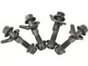 Scion xA Camber and Alignment Kit
 Scion xA Coil Spring Insulator
 Scion xA Coil Springs
 Scion xA Control Arm
 Scion xA CV Boot
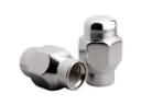 Scion xA Lug Nuts
 Scion xA Shock Absorber
 Scion xA Shock and Strut Boot
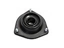 Scion xA Strut Mounts
 Scion xA Sway Bar Bushing
Browse Scion xA Axle Shaft by Years
2006
2005
2004