×
ToyotaParts- Hello
- Login or Register
- Quick Links
- Live Chat
- Track Order
- Parts Availability
- RMA
- Help Center
- Contact Us
- Shop for
- Toyota Parts
- Scion Parts
My Garage
My Account
Cart
OEM 2006 Scion xA Axle Shaft
Car Axle Shaft- Select Vehicle by Model
- Select Vehicle by VIN
Select Vehicle by Model
orMake
Model
Year
Select Vehicle by VIN
For the most accurate results, select vehicle by your VIN (Vehicle Identification Number).
4 Axle Shafts found

2006 Scion xA Outer Joint Assembly
Part Number: 43460-59367$251.16 MSRP: $358.61You Save: $107.45 (30%)Ships in 1-3 Business DaysProduct Specifications- Other Name: Shaft Set, Outboard; CV Joint
- Replaces: 43460-59366
- Condition: New
- SKU: 43460-59367
- Warranty: This genuine part is guaranteed by Toyota's factory warranty.

2006 Scion xA Outer Joint Assembly, Driver Side
Part Number: 43470-59456$212.25 MSRP: $303.05You Save: $90.80 (30%)Ships in 1-3 Business DaysProduct Specifications- Other Name: Shaft Set, Outboard; CV Joint
- Position: Driver Side
- Replaces: 43470-59455
- Condition: New
- SKU: 43470-59456
- Warranty: This genuine part is guaranteed by Toyota's factory warranty.

2006 Scion xA Axle Assembly, Front Passenger Side
Part Number: 43410-52071$414.04 MSRP: $606.77You Save: $192.73 (32%)Ships in 1-3 Business DaysProduct Specifications- Other Name: Shaft Assembly, Front Drive; CV Axle Assembly, Front Left, Front Right; Axle Shaft
- Position: Front Passenger Side
- Replaces: 43410-52070
- Condition: New
- SKU: 43410-52071
- Warranty: This genuine part is guaranteed by Toyota's factory warranty.

2006 Scion xA Axle Assembly, Front Driver Side
Part Number: 43420-52071$359.44 MSRP: $526.77You Save: $167.33 (32%)Ships in 1-3 Business DaysProduct Specifications- Other Name: Shaft Assembly, Front Drive; CV Axle Assembly, Front Left; CV Axle Assembly; GSP Cv Axle; Axle Shaft
- Position: Front Driver Side
- Replaces: 43420-52070
- Condition: New
- SKU: 43420-52071
- Warranty: This genuine part is guaranteed by Toyota's factory warranty.
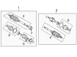
2006 Scion xA Axle Shaft
Looking for affordable OEM 2006 Scion xA Axle Shaft? Explore our comprehensive catalogue of genuine 2006 Scion xA Axle Shaft. All our parts are covered by the manufacturer's warranty. Plus, our straightforward return policy and speedy delivery service ensure an unparalleled shopping experience. We look forward to your visit!
2006 Scion xA Axle Shaft Parts Q&A
- Q: How to service and repair the axle shaft assembly on 2006 Scion xA?A: The front drive shaft assembly requires removal of the front wheel and engine cover, draining of the transaxle fluid, and liberal use of the special tools to disassemble various parts. Check and remove drive shaft, replace with new parts and make sure that the torque requirements are met. Lastly, wheel alignment and check fluid levels.
Related 2006 Scion xA Parts
 2006 Scion xA Wheel Hub
 2006 Scion xA CV Boot
 2006 Scion xA Coil Spring Insulator
 2006 Scion xA Coil Springs
 2006 Scion xA Control Arm
 2006 Scion xA Control Arm Bolt
 2006 Scion xA Lug Nuts
 2006 Scion xA Shock And Strut Mount
 2006 Scion xA Shock and Strut Boot
 2006 Scion xA Sway Bar Bushing
 2006 Scion xA Sway Bar Kit
 2006 Scion xA Trailing Arm Bushing