×
ToyotaParts- Hello
- Login or Register
- Quick Links
- Live Chat
- Track Order
- Parts Availability
- RMA
- Help Center
- Contact Us
- Shop for
- Toyota Parts
- Scion Parts
My Garage
My Account
Cart
OEM 2005 Scion xA Axle Shaft
Car Axle Shaft- Select Vehicle by Model
- Select Vehicle by VIN
Select Vehicle by Model
orMake
Model
Year
Select Vehicle by VIN
For the most accurate results, select vehicle by your VIN (Vehicle Identification Number).
4 Axle Shafts found

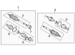
2005 Scion xA Outer Joint Assembly
Part Number: 43460-59367$251.16 MSRP: $358.61You Save: $107.45 (30%)Ships in 1-3 Business DaysProduct Specifications- Other Name: Shaft Set, Outboard; CV Joint
- Replaces: 43460-59366
- Condition: New
- SKU: 43460-59367
- Warranty: This genuine part is guaranteed by Toyota's factory warranty.

2005 Scion xA Outer Joint Assembly, Driver Side
Part Number: 43470-59456$212.25 MSRP: $303.05You Save: $90.80 (30%)Ships in 1-3 Business DaysProduct Specifications- Other Name: Shaft Set, Outboard; CV Joint
- Position: Driver Side
- Replaces: 43470-59455
- Condition: New
- SKU: 43470-59456
- Warranty: This genuine part is guaranteed by Toyota's factory warranty.

2005 Scion xA Axle Assembly, Front Passenger Side
Part Number: 43410-52071$414.04 MSRP: $606.77You Save: $192.73 (32%)Ships in 1-3 Business DaysProduct Specifications- Other Name: Shaft Assembly, Front Drive; CV Axle Assembly, Front Left, Front Right; Axle Shaft
- Position: Front Passenger Side
- Replaces: 43410-52070
- Condition: New
- SKU: 43410-52071
- Warranty: This genuine part is guaranteed by Toyota's factory warranty.

2005 Scion xA Axle Assembly, Front Driver Side
Part Number: 43420-52071$359.44 MSRP: $526.77You Save: $167.33 (32%)Ships in 1-3 Business DaysProduct Specifications- Other Name: Shaft Assembly, Front Drive; CV Axle Assembly, Front Left; CV Axle Assembly; GSP Cv Axle; Axle Shaft
- Position: Front Driver Side
- Replaces: 43420-52070
- Condition: New
- SKU: 43420-52071
- Warranty: This genuine part is guaranteed by Toyota's factory warranty.
2005 Scion xA Axle Shaft
Looking for affordable OEM 2005 Scion xA Axle Shaft? Explore our comprehensive catalogue of genuine 2005 Scion xA Axle Shaft. All our parts are covered by the manufacturer's warranty. Plus, our straightforward return policy and speedy delivery service ensure an unparalleled shopping experience. We look forward to your visit!
2005 Scion xA Axle Shaft Parts Q&A
- Q: How to overhaul the axle shaft on 2005 Scion xA?A: The process to overhaul the front drive shaft begins with draining manual transaxle oil using 39 Nm (398 kgf-cm, 29 ft. lbs.) torque but the automatic transaxle fluid requires 25 Nm (255 kgf-cm, 18 ft. lbs.) torque. When working on the front wheel and engine under cover LH you need to remove the front axle hub LH nut while using Special Service Tool: 09930-00010 supported by a hammer to push up the retaining tabs and liberate the staked portion of the nut to prevent screw damage to the drive shaft. Reset the speed sensor front LH from the steering knuckle when you separate it with bolt and clip removal after ensuring the sensor stays undamaged. The stabilizer bar front gets separated first by using a spanner (10 mm) to remove the bolt while holding it followed by removing the nut and then separating the cushion retainers and cushions. Break apart the front suspension arm sub-assembly lower No.1 LH by unscrewing its clip and nut followed by tool usage of Special Service Tool: 09628-00011 to detach it from the steering knuckle. The LH tie rod end sub-assembly needs its cotter pin and nut removed prior to separating by using Special Service Tool: 09628-62011 on the steering knuckle. A plastic hammer must be used to separate the front drive shaft assembly LH from the front axle assembly LH but the boot and speed sensor rotor must be kept free from damage. Use Special Service Tool 09520-01010, 09520-24010 (09520-32040) and a brass bar with a hammer to remove the front drive shaft assembly LH then again apply caution to the oil seal and boot. The front axle assembly LH should be repaired to avoid damaging the hub bearing while inspecting both the front drive shaft assembly LH for play along with its boot condition. Use screwdriver or needle nose pliers to remove the inboard joint boot LH No.2 clamp before removing the inboard joint boot LH clamp according to the same method. The inboard joint boot needs to be dismounted from the inboard joint assembly LH before cleaning old grease from the assembly LH and application of matchmarks to proceed with its separation from the outboard joint shaft assembly. Users must first remove the inner LH shaft snap ring with snap ring expanders before marking both the outboard joint shaft assembly and tripod joint assembly for brass bar/hammer removal of the tripod joint assembly while maintaining roller protection. The technician must detach the inboard joint boot LH No.2 clamp followed by the inboard joint boot and then the inboard joint boot LH clamp. The procedure for removing the drive shaft damper setting clamp and drive shaft damper RH from the RH side matches the LH side method. A screwdriver unlocks the outboard joint boot LH No.2 clamp and outboard joint boot LH clamp and enables removal of the boot from the outboard joint shaft assembly after the old grease must be cleaned from the joint. Install the new dust cover LH using press and Special Service Tool: 09527-10011 (a press) while ensuring the tool remains undamaged. The correct procedure demands an installation of the new LH hole snap ring followed by spline spline vinyl tape wrapping then precise placement of new parts while packing the outboard joint assembly LH should receive 155 to 170 g of grease. Check both outboard joint boot clamp positions by measuring their clearance until it reaches 0.8 mm (0.031 inch) or less. keep the drive shaft damper RH in proper position and attach the damper setting clamp correctly. Install the inboard joint assembly LH while using matchmarks for alignment and grease it with 125 to 135 g followed by inboard joint boot installation and clamp securing. The installation of the front drive shaft assembly LH requires gear oil for M/T or ATF for A/T coatings on the spline while ensuring a proper position of the hole snap ring and checking for boot damage and play in the shaft. Perform another installation of the front drive shaft assembly RH before adding the front axle assembly LH while ensuring no damage is inflicted on the outboard joint boot or speed sensor rotor. The procedure requires installation of the tie rod end sub-assembly LH with 49 Nm torque (500 kgf-cm, 36 ft. lbs.) before adding a new cotter pin after which the front suspension arm sub-assembly lower No.1 LH uses 98 Nm torque (1,000 kgf-cm, 72 ft. lbs.) and features a new clip. The stabilizer bar front requires installation with cushion retainers and nut before torquing to 18 Nm (184 kgf-cm, 13 ft. lbs.). Next install the speed sensor front LH with a torque of 29 Nm (300 kgf-cm, 22 ft. lbs.) and on the steering knuckle with a torque of 8.0 Nm (82 kgf-cm, 71 inch lbs.). After installing the new hub LH nut with 216 Nm (2,200 kgf-cm, 159 ft. lbs.) torque you should stake it. Then proceed to replace the engine under cover LH and front wheel while torquing to 103 Nm (1,050 kgf-cm, 76 ft. lbs.). Complete the process by adding and inspecting manual and automatic transaxle fluids as well as adjusting front wheel alignment and checking ABS speed sensor signal.
Related 2005 Scion xA Parts
 2005 Scion xA Wheel Hub
 2005 Scion xA CV Boot
 2005 Scion xA Coil Spring Insulator
 2005 Scion xA Coil Springs
 2005 Scion xA Control Arm
 2005 Scion xA Control Arm Bolt
 2005 Scion xA Lug Nuts
 2005 Scion xA Shock And Strut Mount
 2005 Scion xA Shock and Strut Boot
 2005 Scion xA Sway Bar Bushing
 2005 Scion xA Sway Bar Kit
 2005 Scion xA Trailing Arm Bushing