×
ToyotaParts- Hello
- Login or Register
- Quick Links
- Live Chat
- Track Order
- Parts Availability
- RMA
- Help Center
- Contact Us
- Shop for
- Toyota Parts
- Scion Parts
My Garage
My Account
Cart
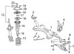
OEM 2005 Scion xA Control Arm
Suspension Arm- Select Vehicle by Model
- Select Vehicle by VIN
Select Vehicle by Model
orMake
Model
Year
Select Vehicle by VIN
For the most accurate results, select vehicle by your VIN (Vehicle Identification Number).
2 Control Arms found


2005 Scion xA Lower Control Arm, Passenger Side
Part Number: 48068-59065$253.84 MSRP: $362.42You Save: $108.58 (30%)Ships in 1-3 Business DaysProduct Specifications- Other Name: Arm Sub-Assembly, Suspension; Suspension Control Arm, Front Right; Control Arm Assembly; Arm Sub-Assembly, Front Suspension, Lower Passenger Side; Control Arm
- Position: Passenger Side
- Part Name Code: 48068
- Item Weight: 6.00 Pounds
- Item Dimensions: 17.7 x 4.9 x 16.9 inches
- Condition: New
- Fitment Type: Direct Replacement
- SKU: 48068-59065
- Warranty: This genuine part is guaranteed by Toyota's factory warranty.
2005 Scion xA Lower Control Arm, Driver Side
Part Number: 48069-59065$253.84 MSRP: $362.42You Save: $108.58 (30%)Ships in 1-3 Business DaysProduct Specifications- Other Name: Arm Sub-Assembly, Suspension; Suspension Control Arm, Front Left; Control Arm Assembly; Arm Sub-Assembly, Front Suspension, Lower Driver Side; Control Arm
- Position: Lower Driver Side
- Part Name Code: 48069
- Item Weight: 6.10 Pounds
- Item Dimensions: 18.6 x 4.9 x 16.9 inches
- Condition: New
- Fitment Type: Direct Replacement
- SKU: 48069-59065
- Warranty: This genuine part is guaranteed by Toyota's factory warranty.
2005 Scion xA Control Arm
Looking for affordable OEM 2005 Scion xA Control Arm? Explore our comprehensive catalogue of genuine 2005 Scion xA Control Arm. All our parts are covered by the manufacturer's warranty. Plus, our straightforward return policy and speedy delivery service ensure an unparalleled shopping experience. We look forward to your visit!
2005 Scion xA Control Arm Parts Q&A
- Q: How to Service and Repair the Control Arm in the Front Suspension on 2005 Scion xA?A: The procedure for lower No.1 LH front suspension arm sub-assembly replacement starts by taking off the front wheels and the hood sub-assembly before suspending the engine assembly. Special Service Tool 09628-00011 enables you to separate the lower suspension arm from the steering knuckle when both components are stripped of their clip and nut. The replacement procedure also applies to the second No.1 RH front suspension arm. After you hold the front stabilizer bolt with a spanner to detach the nut, remove the retainers and cushion from both sides. The 4 bolts and 4 nuts must be removed from the power steering link assembly before suspending it. The removal process starts with removing the front suspension member reinforcement LH and RH while detaching the pressure feed tube assembly bolt before taking out each bolt on the front suspension member reinforcement LH and RH. To detach the front suspension crossmember sub-assembly start by eliminating the bolt with 2 nuts while using a jack to support it and lastly remove 4 bolts. Separate the front suspension arm sub-assembly lower No.1 LH through the removal of 2 bolts with a subsequent nut extraction but avoid turning this nut during the process. Stick the ball joint stud on the front suspension arm sub-assembly lower No.1 LH back and forth five times before installing the nut. Then use a torque wrench to make the nut turn with no more than 5.0 Nm (51 kgf-cm, 44 inch pounds) torque. Secure the front suspension arm sub-assembly lower No.1 LH by fastening its 2 bolts with a nut. Insert the front suspension crossmember sub-assembly using Special Service Tool: 09670-00010 to match the holes while you install it via 4 bolts that require Bolts A torque set to 70 Nm (715 kgf-cm, 52 ft. lbs.) and Bolt B set to 116 Nm (1,180 kgf-cm, 86 ft. lbs.) and where you finish with bolt and 2 nuts requiring 80 Nm (816 kgf-cm, 59 ft. lbs.). Secure the front suspension member reinforcement LH and RH through 2 bolts with recommended torque value of 47 Nm (480 kgf-cm, 35 ft. lbs.). Attach the power steering link assembly to 4 bolts and 4 nuts by torquing each bolt to 74 Nm (755 kgf-cm, 55 ft. lbs.). After connecting the pressure feed tube assembly to its bolt with 7.8 Nm (80 kgf-cm, 69 inch lbs.), avoid rotating the nut. Add the stabilizer bar front components along with retainers and cushion before tightening the nut to 18 Nm (180 kgf-cm, 13 ft. lbs.) while applying support to the lower arm with a jack. Then repeat the procedure on the opposite side. Connect the front suspension arm sub-assembly lower No.1 LH to the steering knuckle with the nut at 98 Nm (1,000 kgf-cm, 72 ft. lbs.) and install a new clip then tighten the nut additional 60 degrees when the clip holes are off. The procedure of attaching the front suspension arm sub-assembly lower No.1 RH requires replication. Connect the front wheels with 103 Nm (1,050 kgf-cm, 76 ft. lbs.), then fully tighten the front suspension arm sub-assembly lower No.1 LH while using 2 bolts to secure Bolt A at 88 Nm (900 kgf-cm, 65 ft. lbs.) and Bolt B at 132 Nm (1,350 kgf-cm, 97 ft. lbs.) without turning the nut. The last step involves checking the hood sub-assembly together with adjusting the front wheel alignment.
Related 2005 Scion xA Parts
 2005 Scion xA Wheel Hub
 2005 Scion xA Axle Beam Mount
 2005 Scion xA Bump Stop
 2005 Scion xA Coil Springs
 2005 Scion xA Control Arm Bolt
 2005 Scion xA Front Cross-Member
 2005 Scion xA Shock Absorber
 2005 Scion xA Shock And Strut Mount
 2005 Scion xA Shock and Strut Boot
 2005 Scion xA Sway Bar Bracket
 2005 Scion xA Sway Bar Bushing
 2005 Scion xA Sway Bar Kit