×
ToyotaParts- Hello
- Login or Register
- Quick Links
- Live Chat
- Track Order
- Parts Availability
- RMA
- Help Center
- Contact Us
- Shop for
- Toyota Parts
- Scion Parts
My Garage
My Account
Cart
OEM Scion xD Rack And Pinion
Steering Gear- Select Vehicle by Model
- Select Vehicle by VIN
Select Vehicle by Model
orMake
Model
Year
Select Vehicle by VIN
For the most accurate results, select vehicle by your VIN (Vehicle Identification Number).
2 Rack And Pinions found

Scion xD Gear Assembly Part Number: 45510-52211
$582.13 MSRP: $853.12You Save: $270.99 (32%)Ships in 1-3 Business DaysScion xD Gear Assembly Part Number: 45510-52191
$626.62 MSRP: $918.32You Save: $291.70 (32%)Ships in 1-3 Business Days
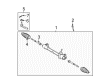
Scion xD Rack And Pinion
Choose genuine Rack And Pinion that pass strict quality control tests. You can trust the top quality and lasting durability. Shopping for OEM Rack And Pinion for your Scion xD? Our website is your one-stop destination. We stock an extensive selection of genuine Scion xD parts. The price is affordable so you can save more. It only takes minutes to browse and find the exact fit. Easily add to cart and check out fast. Our hassle-free return policy will keep you stress-free. We process orders quickly for swift delivery. Your parts will arrive faster, so you can get back on the road sooner.
The Rack And Pinion has a critical role as it creates an impressive addition to the Scion xD vehicles that are famous for their dependability and control they offer automobile drivers. This steering gear changes the rotation of the steering wheel into accurate side movement of the front wheels to provide operational efficiency. The Rack And Pinion system is mainly of the power assisted type; the steering operates through a hydraulic or an electrical power assist which makes it a special offer of the auto industry. Regarding its design, Rack And Pinion steering system in Rack And Pinion also affects its efficiency; it features straight gears that make the system work cooler and consequently have less propensity to wear out than helical gears. That is why the stability of this component is significant for regulation and the possible driving scenarios. The Rack And Pinion can be used with several xD models; a key component in boosting the car's performance and safety status. Also, the safety requirements are also well taken care of in the Scion xD with features such as the anti-lock brake and traction control features that compliment the Rack And Pinion while enhancing the safety of the vehicle. While it is universally known that Rack And Pinion has a long lasting feature and another one, the xD is not just considered a car with the optimal designs but also enhanced performance among car drivers, thanks to this worm.
Scion xD Rack And Pinion Parts and Q&A
- Q: How to install the power Rack And Pinion on Scion xD?A:Start power steering rack and pinion installation with the tie rod end sub-assembly LH which requires proper matchmark alignment when installed onto the rack and pinion. After toe-in adjustment tighten the lock nut to 7.5 Nm (76 kgf-cm, 66 in-lbf). Repeat the same step for tie rod end sub-assembly RH. Position the power steering rack and pinion on the front suspension crossmember through 2 bolts and 2 nuts which must torque to 96 Nm with a prevention of nut rotation. The front suspension crossmember needs transmission jack support to temporarily attach it to the body structure through six bolts. Use Special Service Tool: 09670-00011 in the datum holes of the front suspension crossmembers RH and LH alternately to tighten bolts A, B, and C to the specified torques of 70 Nm (714 kgf-cm, 52 ft-lbf for Bolt A), 160 Nm (1,631 kgf-cm, 118 ft-lbf for Bolt B) and 95 Nm (969 kgf-cm, 70 ft-lbf for Bolt C), with vertical insertion of the tool. Fix the engine moving control rod through a bolt which needs tightening to 120 Nm (1,224 kgf-cm, 89 ft-lbf). The installation of front suspension lower arms LH and RH begins with the same approach and continues with the placement of front stabilizer link assemblies LH and RH. Next install the tie rod end sub-assemblies LH and RH using the same steps for both sides. The following steps involve installing the front wheel while tightening to 103 Nm (1,050 kgf-cm, 76 ft-lbf) followed by attaching the No. 1 steering column hole cover sub-assembly. Reposition the tie rod end sub-assemblies on both sides by using the exact procedure which applies to both LH and RH elements. Fasten the front wheel with a torque of 103 Nm and proceed by installing the No. 1 steering column hole cover sub-assembly through securing clip B onto the body and column No. 1 with clip A while guaranteeing the lip portion remains undamaged. Reposition the sliding yoke of the rack and pinion sub-assembly onto the intermediate shaft before tightening bolt A with yoke and bolt A at 35 Nm (357 kgf-cm, 26 ft-lbf). Keep the column hole covered by installing the silencer sheet with 2 clips and return the floor carpet. Complete the installation by connecting the cable to the negative terminal with 5.4 Nm torque (55 kgf-cm, 48 in-lbf) and position the wheels straight ahead then inspect the wheel alignment.